|
||||
|
Click on the above to visit our featured advertisers. Tell them you saw their ad on Wiring for DCC!
My new DCC book! Wiring Turnouts Welcome to the website that coined the phrase "DCC Friendly!" This is the most popular section of this web page! If you are a manufacturer, talk to your DCC customers. Consider making DCC friendly turnouts - I tell you how below. Modelers, write your favorite manufacturer. Tell them you would like DCC friendly turnouts. Check out Dale Muir's railroad information page: https://dalemuir.com/ for turnout terminology. To see a schematic of a turnout wired to trackwork, see the trackwork section of this web page, suggestion 5-7. Check out George T. Galyon's HO Turnout Compendium. George discusses all sorts of details about installing the industry's most popular turnouts. The compendium is in .pdf format. You will need Adobe's Acrobat Reader. Get it at: https://get.adobe.com/reader/otherversions The Wiring For DCC Turnout Hall of Fame The following manufacturers make turnouts that are DCC friendly (compatible): Atlas, Kato, Micro Engineering, Roco, Peco, Walthers For all other turnouts, see menu bar on right.
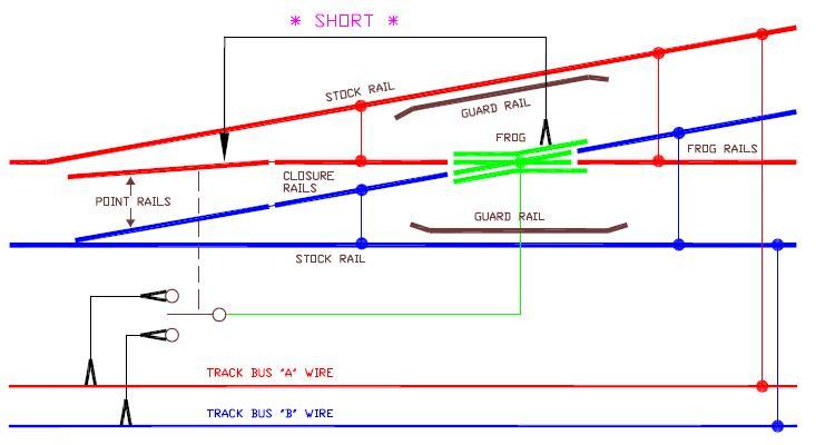
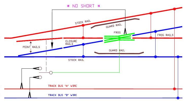
INFORMATION #2-17: What is a DCC Friendly Turnout? These diagrams "say" it better than words!
These diagrams are examples of DCC friendly turnouts and what makes them so. In the above diagrams I have also included how you would power route the frog. See the appropriate section below for your favorite switch. Power routing of the frog, and using a light bulb for short circuit protection, is optional. See section below for more on power routing. I show jumpers (called bonds) between the point rails and closure rails. I personally like turnouts that have the point rail and closure rail that are one piece and therefore eliminates the need for bonds. Commercial turnouts that have point rails hinged to the closure rails, may eventually need a bond if they develop poor electrical connection at the hinge. You are wise to put the bond in now as the hinge could become a hot spot should a short occur. However, if you are using a DCC friendly turnout, the likelihood of a short developing is much less! Beginners, you can ignore this: Those that have some electrical experience will recognize the switch I have drawn as a SPDT (single pole double throw) center off switch. You would be right to say that a simple SPDT (without center off) is more common and would work just as well on a DCC friendly turnout. Absolutely correct. I drew it as I did to make it easier for beginners to visualize the SPDT working with the turnout. Features that Make a Turnout DCC Friendly: Points: Frog: How to Tell if Your Turnout is Not DCC Friendly: The easiest thing to do is check the left menu bar. It lists the most popular manufacturers and identifies the turnout as DCC friendly or not. Also, click on the link and read about your turnout. If you have a turnout not listed, look for any of the following. There are two key areas of a turnout that make it not DCC Friendly. If you have any of the identified features under a single group, you have a turnout that is partially not DCC Friendly. If you have at least one feature under both groups, then you have a turnout that is not DCC Friendly at all. Find a listed manufacturer that is closest to the turnout you have for information on how to use your turnout. Non-DCC Friendly Features: Points: Frog: A turnout that works well that does not look like the above diagrams is not DCC friendly! It is important to note that the definition of DCC friendliness is "objective," not "subjective." In other words, a DCC friendly turnout is not one that just happens to work well even though it does not look like the above diagrams. If a turnout does not have the point and stock rail at the same polarity and a single polarity (controlled by the switch machine) at the frog, it is not a DCC friendly turnout. A DCC turnout tolerates imperfections in trackwork and wheels. If you have a turnout that is working well, you don't have a DCC friendly turnout, you have good trackwork and wheels. For another perspective on DCC friendly turnouts, see Mark Gurries' website at:: https://sites.google.com/site/markgurries/home/dcc-friendly-switches
SUGGESTION #2-22: A Practical Alternative to Making A Turnout DCC Friendly - Half Friendly! There are two key components to making a turnout DCC friendly. If you have a power routed turnout, the first design component of a DCC friendly turnout, the point and adjacent stock rails at the same polarity, can be difficult to implement. In most cases, you will need to use a circuit board throw bar. This may be beyond your soldering ability. This will be even harder if turnout is already installed in a layout and worse if it is in a difficult to work on location. The second design component, all aspects of the frog at the same polarity does not require you to be very good with a soldering iron and can be done to a turnout that is installed in a layout. Pretty much all you have to do is cut on either side of the frog with a razor saw and drop a power routing feeder to it. If the frog rails are already insulated (on an existing layout) or you are planning to do so on a new layout, then you need only do one cut prior to the frog on the closure rails. This is not as "ideal" as a fully DCC friendly turnout. You will still be susceptible to wheels shorting between the point and stock rails. Of course, if you wheels are way out of gauge or your turnouts are, then you really do have a mechanical problem you should solve and you should not be looking for a work-around. Assuming your wheels are in gauge, than an occasional derailment could still cause a short between these two rails. While I have not done a serious study of which area of a turnout shorts the most, it seems that wheels picking points is where a derailment frequently occurs. The train frequently makes it past this point. The short occurs when the twisted truck hits the frog. While it would be nice to know if this is fact, it is not important; a half DCC friendly turnout is better than not at all. If going the full DCC friendly route seems like too much trouble, or is too much trouble, give this idea a thought as you consider your options below.
SUGGESTION #2-20: Use a Car Tail Light Bulb to Reduce System Shutdown Due to a Short. One of the diagrams in the top section shows a light bulb being used for short circuit protection. This is primarily intended for overzealous, junior (or soon to be demoted!) engineer who runs into the turnout without having the points being thrown their way. This would cause a short on a power routed frog turnout of any kind; DCC friendly or not. (Insulated frog turnouts do not have this minor problem and do not need the light bulb. Unfortunately, many locomotives cannot make it across an unpowered or insulated frog.) The light bulb is optional with either of the switch types shown. I suggest that you use a bulb for the first type of turnout. I definitely recommend it for the second type. It is more likely with this second switch type that a person might accidentally get too close to the power routed portion of the switch and short out the system. See the track wiring section for more information on using light bulbs. Let the bulbs dangle so they do not touch anything. You do not want to risk fire. If a short does occur that is guarded by a bulb, you will know it. Not only will your train stop, but your feet will light up, too!
INFORMATION #2-15: What is Power Routing? This section is for those that are unfamiliar with power routing. Power routing was popular during the days of DC block control. It was a way for using specially built turnouts to turn the power on or off to a siding or yard track automatically. For example, this allowed you to pull a train into a siding and have it stay there automatically when the turnout was thrown back to the main line. Generally, no additional switches or wiring was necessary. Given that DC block operations required control panels and lots of switches, you can see the appeal; especially where a yard was involved. On a turnout, you must power route the frog or electrically insulate it. Now look at the frog of a turnout at the top of this section. When a train goes straight through, the left wheels will be in contact with the frog. When a train takes the diverging route, the right wheels will be in contact with the frog. Either the frog supplies the right polarity power to the wheels or insulate the frog and not supply any power at all. Not supplying power is the easy way out. Unfortunately, short locomotives that only have a few wheels picking up power may stall on an insulated frog. Even long articulateds, like those from Rivarossi, only have two closely placed wheels on each side. Hence the need to route the correct polarity power to the frog - power routing! The switch shown power routing the frog can be implemented in any one of a number of ways. It can be:
- built into the switch machine like a Tortoise or NJ International. The important thing is that the switch is flipped at basically the same time the points flip.
RECOMMENDATION #2-16: A DCC Friendly Turnout Solves the Problem of Shorting When Using Auxiliary Contacts! For those using power routed turnouts with wipers on the points, you will want to read this. If you are using ground throws, you can use a switch built into some of them. Or you can add a micro switch. Burying a micro switch is more work, but the switch will last practically forever. For electrically powered turnouts, it is common practice to use contacts built into the switch machine or add a micro switch if no contacts are available. With typical power routed turnouts, the reliability conscientious modeler is faced with dilemma. If the modeler counts on the manufacturer supplied point wipers (look at a Shinohara or Peco for example) to power route the frog, the modeler knows eventually these will fail and power routing via contacts or micro switch will be necessary. If the modeler adds the contacts or micro switch, a short may occur if the micro switch or contacts switch when one of the point rails is still in contact with wrong rail. So the modeler is forced to disable the wipers on the turnout to eliminate the potential of a short. With DCC friendly turnouts, the point and the stock rail are at the same potential. So there is no potential of a short. Point wipers or not, there is simply nothing to worry about!
RECOMMENDATION #2-1: Power Route ONLY the Frog. One way to make troubleshooting easier, is to limit how far reaching trouble can be. Power route only the frog. Some turnouts are designed such that the frog cannot be easily separated from the frog rails. That is fine. You may power route the little bit leaving the turnout. Furthermore, if you have blocks where they end by the fouling point of the turnout, it is logical to include this little extra bit of rail. This is how my railroad is set up. Power route no more than this! Besides limiting how far trouble can get, consider the 5 amp short. Points are not a good way of routing power to the closure rails. They are even worse for power routing a siding. Five amps at 16 volts is 80 watts of power. How hot is a 75 watt light bulb? Any resistance in the points or small or cheap switches power routing a frog, will "take" that 75 watts during a short. Your plastic ties could melt! Wooden ties could catch fire! Homasote could catch fire!
RECOMMENDATION #2-2: Don't Power Route ANY Sidings. Not Even Single Stub Sidings.Some of you want to power route stub sidings. Please do not! I have heard all the reasons.* Keep things consistent! Run two feeder wires to that stub siding just like you are going to do to everywhere else. *You want to park a locomotive on a siding, right? "I do not have DCC in all my locomotives" you say. I do not either; not even close. But, DCC is like CD's. CD's were much more expensive than vinyl albums. "I am only going to buy CD's of albums I know I am going to like." How long did that last? Me, too. One way or another, all of us are going to find a way to afford to put DCC decoders in all of our locomotives that we want to run. Wire for DCC! If your budget is tight, look for $17 decoders. They are out there now!
SUGGESTION #2-3: Use DCC Friendly Turnouts Whenever Possible.There are two reasons for doing this. Both relate to short circuits during DCC operation. Shorts can occur when power pick up by the points occur on both sides at the same time. Also, when metal wheels roll through and contact both the stock rail and points at the same time. A short can cause annoying interruptions to an entire layout. With 13 locomotives running, this was driving us nuts! The other reason is that a DCC short can have about 75 watts of power flowing through it. Any points that have some resistance can cause a light bulb's worth of heat. This might be where the points contact the stock rails, where the wheels touch rails, or that joiner you use to connect the points to the closure rails. This light bulb's worth of heat can melt ties and perhaps cause a fire. By attaching the stock rails to the point rails, a short by the wheels or the points to both stock rails is now unlikely. This alteration also eliminates the joiners between the closure rails and the points from being a potential hot spot. As far as I know, all DCC power boosters have short circuit protection. Unfortunately, as a minimum, they shut down everything that booster is powering — commonly the entire railroad! With some systems that have multiple boosters, system wide shut down is a result. Some of us solve this problem by placing car brake light bulbs in series with track feeder sections. The bulb prevents a dead short from being seen by the booster. Therefore, all other locomotives on that booster keep running; provided they are on a different track feeder section. An added bonus is that the light lights up indicating the location of the short! While this does prevent a short, it still permits a fair amount of power to flow — about 25 watts. Needless to say, this still a good bit of heat. The bottom line is to do what is possible to avoid shorts. A DCC friendly turnout, as a minimum, has the points wired to the stock rails. As a practical matter, it will also probably have the rails leading from the points to the frog wired likewise. Also, the rails leaving the frog can be wired to the appropriate stock rail. In short, Atlas is a good example of a DCC friendly turnout. (Note: This does not mean that the Atlas is the best DCC friendly switch. It is a good example of a turnout that is not power routed and is wired in the manner I suggest.) It takes me about 45 minutes to make a Walther's (Shinohara) DCC friendly. Follow the directions and make 1 turnout DCC friendly. Then make them assembly line fashion. Doing it this way, I can do 4 turnouts in 3 hours.
INFORMATION #2-11: Owners of Existing Layouts. DCC friendliness is desirable, but not essential. If you have an existing layout, you need not consider uprooting your turnouts to make them DCC friendly. That is a heck of a lot of work! The risk of damage to the turnouts may be too high. Depending on the make of turnout, the degree of effort may vary. Evaluate the situation based on your ability to do the job successfully without doing harm to your turnouts. For the moment, do not worry about DCC friendliness. Definitely forget those that are hard to reach or in tunnels. What do you do if you forgo making your turnouts DCC friendly? Do not worry, the locusts will not come. There are ways to avoid being eternally cursed. The easiest thing, but definitely not the cheapest, is to use lots of boosters. Each booster would control a small, rather than a large, area of your railroad. You could go as far as having a booster for each town. In this case, only one operator would probably be affected. Your level of frustration will not be any worse than it is now with your existing railroad and rolling stock. A note for the old Digitrax Big Boy owners: Shorts on the booster attached to the throttle acting as a command station may shut down the whole railroad. So some people do not use it attached to any track. Or they use it with track that sees little activity. Definitely do not make it part of a yard! The Chief does not have this problem. So if you have not upgraded to the Chief, this may be your incentive. Everybody: A lot cheaper and actually easier than converting your turnouts, is to use a light bulb in series with the feeders to each turnout. Isolate each turnout by cutting all six rails going to it so you can feed it separately. Only one of the feeders needs the bulb. The bulb has its draw back so be sure to read the track wiring section covering the bulbs. You can also put a circuit breaker in series with a turnout. The circuit breakers, while I think are quite reasonably priced, are not inexpensive and can add up to be more than going with a lot of boosters. If you want to use the circuit breakers, feed several turnouts through a single breaker. This will make the cost more palatable to you and make this an attractive alternative to the other options.
SUGGESTION #2-14: Drop Feeders from Your Point Rails OR Solder Wires From Your Closure Rails to Your Point Rails. Drop a feeder from the point rail to the bus. Alternately, solder jumpers (called bonds) from each closure rail to the corresponding point rail. This ensures good electrical contact as the years go by. This will also prevent the hinge point from becoming a hot spot should a short occur. Do this even if you have a turnout with wipers that bring electrical power to the points from the stock rails. Sooner or later, this will also become a spot of poor electrical contact or a hot spot during a short. Note: Since some switch machines do not have the power to operate a turnout with bonds on it, dropping a feeder to the bus from the point is now the preferred approach. This is a solution everyone can use! Do this while the switch is new and easy to solder to! It will be a lot more work later. Retirement is a time to enjoy your trains, not be fussing over your turnouts! Drop Feeders from Points and Soldering Bonds |
HOW TO WIRE TURNOUTS |
Introduction
When was the last time you bought a turnout and it came with instructions
on how to wire it? Do you get the impression everyone knows
how to wire a turnout but you? This section of the website was
written for you.
This section assumes that you have read everything above that is present on this web page.
This section also assumes you are following the good practice of not power routing through the points. Finally, it is assumed that you will also follow the good practice of not using your power routing turnout to selectively power your sidings.
This section will explain and give you a few examples on how
to wire a turnout. See the web page dedicated to your manufacturer’s
turnout for specific instructions. Each manufacturer specific
web page has a section in blue titled “How
to Wire This Turnout” that
will provide you with the details for wiring
that particular
turnout.
Select
your manufacturer from the menu bar at left. If you do not see
your manufacturer listed, the examples below should provide you
with sufficient guidance.
Generally, turnouts can be classified as one of several types. They are shown below. Additionally, some have an insulated frog that receives no electrical connection. For these, you can look at type 1 to understand how generally to wire that such a turnout. Remember, look at the specific instructions listed with your manufacturer's turnout for details.
Type 1: The frog rails are not electrically connected to the frog - DCC Friendly
This type of turnout is typical of Atlas, Kato, Roco, the new Micro Engineering turnout, and the new Walther's turnout.
Type 2: The frog rails are electrically connected to the frog - DCC Friendly
This type of turnout is typical of Peco and Tillig.
Type 3: Points, frog, and frog rails connected together - not DCC Friendly
Typical of BK Enterpirse, old Micro Engineering, old Walthers/Shinohara.
All the rails in red must be electrically connected to all other red rails. The same goes for the blue and the green rails.
In order to properly wire a turnout, all of the following must be done:
Insulating the frog rails (types 2,3):
You will need insulated joiners as shown. You do not need these insulated joiners on type 1 turnouts.
Connecting the frog (all types):
The rails in green must be connected to your power routing switch or switch machine. The bulb is optional. If your bus is powered through a bulb you do not need a bulb attached to your turnout as shown in the above schematics.
Your power routing switch or switch machine must be connected to your bus shown in red and blue above. Make these connections temporarily. It may be difficult to determine which terminal on your power routing switch goes to which bus. Murphy's Law says that you will get it wrong on the first try.* So make the connection temporarily and then test it. If the locomotive shorts when it hits the frog, you have it wrong and will need to swap the connections on your power routing switch.
*You can try to outsmart Murphy's Law by hooking it up one way and then immediately swapping the wires. However, Murphy's Law says that you will get it wrong on the second try as well.
Below I explain step-by-step how to hook up a Tortoise switch machine to your frog.
Connecting the stock rails (all types):
For all turnouts shown, you must solder a wire to each stock rail and connect it to bus as shown in the color coded drawings above.
Connecting the frog rails (all types):
On some type 1 turnouts, you will need to make a connection to the bus as shown. Most manufacturers of type 1 turnouts connect the frog rails to the stock rails, so you probably don't need to do anything. See the instructions for your particular turnout. Check your turnout with an ohm meter if you are in doubt. If the locomotive stalls on the frog rails, then you probably need to make the electrical connection to the bus.
If you have converted a type 3 turnout to be DCC friendly, you will need to connect the frog rails to the bus.
This instruction does not apply to type 2 turnouts.
Connecting the closure rails (types 1,2):
On some turnouts, you will need to make a connection to the bus as shown. Most manufacturers of type 1,2 turnouts connect the closure rails to the stock rails, so you probably don't need to do anything. See the instructions for your particular turnout. Check your turnout with an ohm meter if you are in doubt.
If your closure rails are not connected to your stock rails, connect your stock rails to your bus. If you have converted a type 3 turnout to be DCC friendly, you will need to connect your closure rails to your bus.
Connecting the point rails (all types):
Unless your turnout has closure rails and point rails that are all one piece with no moving parts (such as Tillig and BK Enterprises), you will need to follow this instruction. This is even if your manufacturer has provided an electrical connection based on a hinge or wipers touching the stock rails. Over time, these connections will become corroded and stop making good electrical contact. You are smarter to make a soldered connection now while the turnout is new because you will have a lot easier time soldering it now then after it has corroded.
For types 1,2: Make a connection between your point rails and the bus.
For type 3: Make a connection between your point rails and your power routing switch or switch machine.
![]()
How to Wire Insulated Frogs (like the Peco Insulfrog).
If you are not familiar with insulated frogs, read the Newbie Notes, Types of Frogs and What type of frog is best for me?
Insulated frogs are simple. You simply don't hook anything up to them. When looking at the drawings in this website, the frog is usually fed by a green wire. You simply don't need the green wire.
Most drawings in this website only show a wired frog. In these cases, you not only don't need the green wire, but you can also do away with the switch that performs the power routing. In the example below, if you were using an insulated frog, you would eliminate the green wire as well as the power routing switch.
Here's a situation where you don't need the green wire going to the frog, but you still need the power routing switch as well as everything else that is shown.
That should do it for you!
![]()
Getting the Frog Polarity Right
Typically, a frog is power routed through some sort of electrical switch. The switch may be attached to a ground throw or a switch machine. You will need to hook your bus wires to the switch. Which way do you hook the wires? If you hook them up wrong, locomotives will short when they cross the frog.
There are at least four ways to get the frog polarity
right:
1. Carefully think it through. Murphy's Law will make sure you
get it wrong.
2. Use a meter.
3. Use a locomotive.
4.
Use Allan's quick & easy short test described here.
Watch the video!
A meter works. Do you have your meter handy? A locomotive should work, but if you don't have all-wheel power pick-up, you may think you have it right when you don't.
DCC offers you a practical alternative that you never really had before - intentionally testing the frog by shorting it to the appropriate stock, closure, or point rail. You can do this with a piece of wire or a test lead with alligator clips at each end. This method is as fast as a meter but slightly more convenient. You don't have to carry your meter around with its six feet of dangling and tangling test leads. Three short clip leads is all you need. You can buy a set of meter leads for about $6.88 from Mouser. Their part number is 548-287.
Important! What I have shown is for a DCC friendly switch! If you are not using a DCC friendly switch, when I say touch the point rail below, touch the adjacent stock rail instead.
Before I explain how to wire a Tortoise, I want to give you a heads up. I will be referring to the buses below by their color I have shown - red and blue. Your bus wires don't have to be red or blue. In fact, I use black and white for my buses on my model RR. However, putting a white colored wire on a white page wouldn't show up very well on my website. That's the only reason my diagrams don't show white and black wires.
Also, the Tortoise has two internal switches that can be used to power route a frog. You can use either one. To keep confusion down, I will only refer to one of them.
Okay, here goes. It really is simple and will only take about 10 minutes. Once you get one or two of them working, you will be wondering why you were so worried this would be too hard for you to do. It isn't!
Tortoise Diagram
Step 1: Connect a red wire to Tortoise terminal #2, a blue wire to terminal #3, and a green wire terminal #4. (Since frogs are green, your frog wire should be green, too!)
Step 2: Connect the green wire to your turnout's frog. See the top of this page for links to instructions for wiring the turnout of your choice.
Step 3: Temporarily connect the red wire from your Tortoise to your red track bus. Likewise, temporarily connect the blue from your Torotise to your blue track bus. Use the cables with clips that you bought.
Step 4: Now test your frog to see if you got it right. You have a 50/50 chance of having gotten it right - or wrong - depending on your level of optimism. Below are step by step instructions for testing your frog along with diagrams. It will only take you about 15 seconds to test your frog following my instructions below. If this scares you, you can use a locomotive to test your frog. It will take longer than 15 seconds, but it will work. Just be sure your locomotive works going both ways across the turnout as you flip the points.
Step 5: If you find that you have the frog wrong or your locomotive stops when it goes across the frog, no worries. Just swap the temporary connections you made. That is, now connect the blue wire from the Tortoise to the red track bus and connect the red wire from the Tortoise to the blue track bus.
Step 6: After confirming that you have your Tortoise wired correctly to your frog, make your blue and red wire connections permanent. I caution you to do one at a time. If you don't, you may find that forget which way they were and consequently wired them up wrong.
That's it!
 Example demonstrating shorting technique. You
may use this technique with any turnout. In referring to my other
drawings
on this website, the frog area you are trying to power route is
anything I have shown in green.
Example demonstrating shorting technique. You
may use this technique with any turnout. In referring to my other
drawings
on this website, the frog area you are trying to power route is
anything I have shown in green.
While you final goal is a properly wired frog, you will actually be looking for three things.
1. Properly wired frog.
2. Frog polarity reversed (and wrong).
3. No power to the frog — meaning that you don't really have a connection to the frog.
Hook up the bus wires to your frog's power routing switch temporarily as shown above with two of your test or clip leads. It is challenging to clip test leads onto a Tortoise connector — they are too close together. You may find soldering wires on the connector and then clipping to these wires will make things a little easier.
Step 1: Connect your test lead to the frog and touch it to the closed point rail or adjacent stock rail. If you don't get a small spark and/or hear your system shut down, you may be off to a good start.
If your system shorts, you have your connections to your bus backwards. Swap the leads connecting to your bus and try again. If you don't get a short, continue on.
 Step 2: Now touch the test lead to the open point rail or adjacent stock rail. This time you should get a short.
If you didn't get a short for either step 1 or step 2, that means you have a problem with your connection to your frog. Problems I have seen include:
1. The wire you think is going to the frog isn't.
2. The connector on the bottom of the Tortoise is not centered properly.
3. The connections with the clip leads connecting to the bus wires are not making a good connection. Clipping onto the terminals of the Tortoise or via a connector to the Tortoise can be easier said than done.
4. The clip leads connecting to the Tortoise are touching and have everything shorted out.
 Step 3: Throw your turnout. Touch your test lead to the now open points or adjacent stock rail. You should get a short. If you do not and you have followed my directions so far, then you have a bad connection to your power routing switch or Tortoise.
 Step 4: Touch your test lead to the closed point rail or the adjacent stock rail. You should not get a short. After following the above steps, getting to this step should just be a confirmation that you got it right. If your power routing switch is working correctly,
you can fully perform this test in seconds!
Step 4: Touch your test lead to the closed point rail or the adjacent stock rail. You should not get a short. After following the above steps, getting to this step should just be a confirmation that you got it right. If your power routing switch is working correctly,
you can fully perform this test in seconds!
Once you get everything right, remove your clip leads from your power routing switch or Tortoise and make the connections permanent. Make sure you make good notes of which terminal the clip leads were attached to so that you can make your permanent connections correctly. You're done!
Being able to perform the test sequence above is second in importance only to the quarter test. Whenever there is a problem with a power routed frog, I attach a clip lead to a frog and run through these four steps. If all four steps go well, the turnout is okay. If they don't, I know I have a problem to fix.
Understanding and performing the above four steps is also important to my readers because there are a multitude of ways to hook up switch machines. These four steps are the only guaranteed way that will work no matter what method of power routing you are using. Also, it is faster than trying to trace out the wires and making sure you got them right. Just hook up your power routing switch or Tortoise to the bus and perform step 1 and maybe step 2. If you get a short when you shouldn't, swap the clip leads to the bus from your power routing switch or Tortoise and try step 1 and 2 again. This takes just a few seconds.
To view video demonstrating the above, select the file you would like to download from the list below. I have listed the approximate download time for a high speed connection. After you decide which file you would like to download, right click on it. Then select "Save target as" and save the file on your hard drive. After it has completed downloading, go to your hard drive and click on the file. Hit the play button. Enjoy!
mpg hi-rez 226.5 MB approx.
10 minutes
mpg lo-rez 37.4 MB
approx. 4 minutes
wmv 19.2 MB approx.
2 minutes
![]()
SUGGESTION #2-10: Use of Double-Slip Turnouts.
It is a darn complicated thing! At least on one manufacturer, several of the little rail pieces are not powered. Read below how to fix that. If you do not, it is no wonder engines frequently stop on them. Typically, a double-slip is used where very tight switching is required. This means small engines and going slow — no chance to coast through. If you are using a 0-4-0T, you are definitely going to have problems.
Most modelers and clubs will not allow the use of double-slip turnouts; probably mostly because of the problems just mentioned. I cannot attest to whether there are mechanical issues as well since I have heeded the warnings of others and will not use them myself.
Assuming you need to use them, Bob Clegg, BobcatCS@comcast.net has been nice enough to solve the problem of powering them and provide a picture to guide you on doing the same to a Shinohara double-slip. He came up with a pretty simple solution that will power most of the rails.
As you can see, his approach is pretty simple. He writes, "Note that the frog rails of these turnouts are insulated from each other so no insulated rail joiner is needed. If shorts on the frog rail occur, they can be cut and epoxied just beyond the frog. This will limit the dead area to about an inch and a half [37mm] and will not be a problem for any but the shortest wheel based locomotives." {Murphy says: OR the locomotive YOU are trying to run!} Seriously, Bob mentions that you do make sure you have a locomotive that has good power pickup on at least two axles on each side that are more than the 1.5 inches apart.
He mentions that his polarity is the same on all tracks. That means do not try to run a reverse loop through the double-slip. Be creative! You can still use this on a reverse loop if you need to. For example, the balloon track itself can be the reverse loop keeping the polarity on this turnout the same on all four tracks. There are probably lots of ways to have this turnout on a reverse section. Just make sure that your shortest reverse section is at least as long as your longest train. Just in case you really want to run a reverse section through the turnout, that may not be a great idea. I've seen one way this can be done. It is very complex!
A few notes:
1. This is not DCC friendly. Some turnouts this is hard to do to. This
is one of them. I suggest you put a light bulb or an electronic circuit
breaker in series with this turnout if you need to use it.
2. It would also be difficult to run wiring to the points. This may
eventually be a point of failure. If you are very good at soldering,
you might be able to wire power to the points. Otherwise, avoid short
wheel bases.
![]()
Wiring Double Crossovers
For general information on wiring double crossovers, see the description on how to wire a Walthers/Shinohara double crossover in the old Walthers Turnout wiring section.
Walthers' Non-DCC Friendly Double Crossover
![]()
Preventing Wrong-Way Entry Into a Turnout - and - Using Asymmetrical DCC
Contributed by Paul Harman
Do you ever have the problem of a locomotive approaching a turnout when the points are set the wrong way? The locomotive will hit the frog and short out your system. Paul shows a way of stopping a locomotive when the points are set the wrong way for an approaching locomotive. Paul has created two additional electrical sections shown in cyan (light blue) and brown (orange?) below. These zones need to be long enough to stop your longest locomotive. If you are using several locomotives in a multi-unit lash-up, this zone will need to be long enough to stop all of them.
Paul writes:
With conventional electrofrog wiring, the train will bridge the rail
attached to the frog, cause a short circuit and stop, usually causing
the
controller to go into its overload state and shut down.
In the same scenario with DCC, the train will cause a
short circuit, with
probably more current flowing with the potential to melt track components
(and pickups), as well as possibly shutting down the whole layout until
the
points are changed (not possible if it is DCC run from the track power
and
could be in a difficult location).
The answer is to use a double pole switch connected to the tie bar instead of the more usual single pole type, to create isolated sections immediately before the frog, which are switched with the frog. Quite clearly this has little benefit on a conventional layout, but will have considerable benefit on a DCC layout.
While it is unlikely that all situations will be catered for, because to be effective the isolating section will need to be long enough to accommodate the locomotive and any part of the train in front of it, it will be effective for most loco hauled trains. 12 car multiple units will be tricky to accommodate for example, and there could be implications with loss of carriage lighting on multiple units if long isolating sections are used.
If your driving crew doesn't get preoccupied you might not need this, but I find trains often get left to drive themselves at shows when the driver gets chatting to the public!
I use slow motion switch machines that have an auxiliary DPDT relay which are ideal for this or wire in tube with a DPDT slide switch as the actuator for manual points.
How to Wire This Turnout Using a Tortoise
Here is how to wire a turnout for wrong-way entry short protection based on a Peco Electrofrog. Any turnout can be used. Just wire everything in the diagram below the turnout as shown and follow the instructions for the particular turnout. . If you follow my instructions carefully, your turnout with wrong-way entry short protection should be fine the first time.
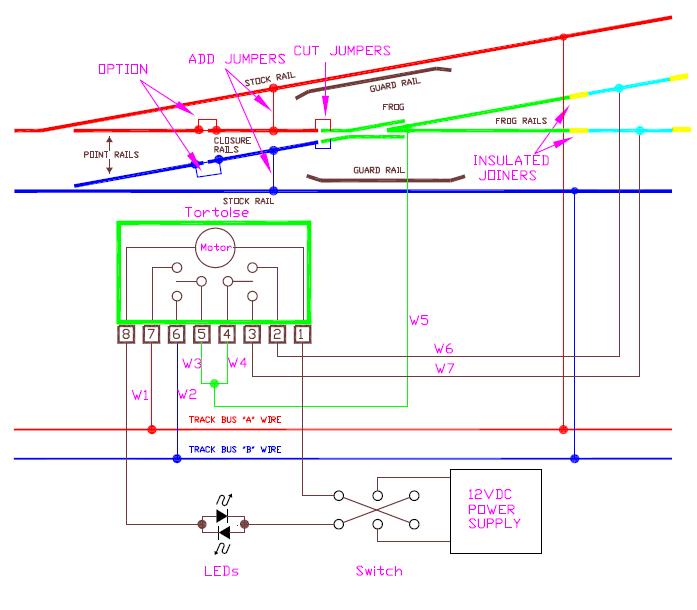
Step 1: Cut the jumpers shown. DO NOT forget to do this. Do it now. If you install the turnout and you don't cut these jumpers you will hate yourself! Add the jumpers shown and add the optional jumpers on the point rails. Go to the section on wiring the Peco Electrofrog for more information about this turnout.
Step 2: Solder wires to the terminals on the Tortoise 6"-18" long. Whatever works for you. Use 20-22 AWG wire.
Step 3: Install your Tortoise switch machine and get it working. Install your LEDs and get them working correctly on your control panel. You may also need to rotate the switch so that the handle points in the right direction.
Step 4: Temporarily connect wires W1 and W2 to the track bus. Follow the instructions on checking your frog polarity in the section on that topic using W3. Reverse W1 and W2 if you need to in order to get the frog polarity correct. When done, you can make the W1 and W2 connections permanent.
Step 5: Connect W3 and W4. If you are using a powered frog turnout, such as the Peco Electrofrog, also connect W5. Connect W5 to your frog. Omit W5 if you are using an unpowered frog.
Step 6: Temporarily connect W6 and W7 to the cyan (light blue) colored rails. Test your wiring by running a locomotive through the turnout and make sure it runs through. Put the locomotive on the other track and try to run the locomotive against the turnout. It should stop without a short. If it shorts, then swap W6 and W7. Check it out and make sure everything works properly. Then make the connections for W6 and W7 permanent.
Using Asymmetrical DCC
Contributed by Paul Harman
Since Paul's original submission above, he has provided the diagram and text below if you are interested in using asymmetrical DCC to stop a train. In case you are wondering, asymmetrical DCC is a way of modifying a standard DCC signal that tells a train to stop without making the lights go out and the sound to stop. You have to use a decoder that supports asymmetrical DCC such as those made by Lenz and Zimo.
There are several advantages to the Lenz/Zimo system including being able to reverse away from the point without having to change it as well as accessing all functions (such as blowing off excess steam or sounding a horn, whistle or bell to wake up the signalman!). BM1s are also cheap to make from five diodes if you do not want to buy them. This diagram does contradict the Lenz rule of thumb for the use of the BM1 ('Right is Right' implying that the BM1 should only be in the right rail) but does make the wiring easier and minimizes the number of insulated rail joints required. The BM1 can be put in the left rail so long as the terminals are reversed.
It is important to note that the ABC system requires that the red and black wires are connected to the correct side pickups in the loco and the Cyan (light blue) and brown (orange) isolated sections are at least as long as the constant braking distance set in the decoder, plus the loco, and any part of the train in front of it (just like 'brake on DC'). For reliable stopping at a precise point regardless of speed, the back EMF needs to be set up and working correctly so that the decoder is able to count the motor revolutions accurately.
There seem to be very few articles discussing use of the ABC braking system, but it is very handy if you have Lenz or Zimo loco decoders and for me is a good reason to buy them. Go to Lenz BM-1 Block Management Module for more on creating asymmetrical DCC.
I hope that this information is useful.
![]()
RECOMMENDATION #2-19: Where to Buy Circuit Board Throw Bars.
Making circuit board throw bars is not fun. In fact, it can be very dangerous! You have a couple of choices.
Fast Tracks Hobbyworks, Inc. sells PC board ties already cut to size and gapped. Order on line at: https://www.handlaidtrack.com/Fast-Tracks-PC-Board-Ties-s/38.htm While you are at it, you may want to pick up a Frog Juicer for your turnout. U.S. modelers will note that Fast Tracks is a Canadian company. I have dealt with several Canadian companies, including Fast Tracks. Shipping cost and normal ground delivery has never been a problem for me.
Cloverhouse has a catalog of strips of PC boards you can use for ties, as well as, all sorts of craftsman supplies and tools. He has sheets and wires of phosphor bronze as well as sheets of brass and nickel silver. Clover House, POB 62, Sebasstopol, CA 95473-0062. www.cloverhouse.com Clover House does not accept phone orders, but you can fax orders to him. Also, you cannot order from the website.
![]()
RECOMMENDATION #2-22: Manual Ground Throws: Power Routing Your Frogs.
Below is how to make a mechanical linkage that power routes your frogs when using ground throws. Since having developed the below described brackets, I discovered frog juicers. They are really slick and simple to use. I now use frog juicers. I leave this description of how to make brackets and linkages for people who want the lowest cost solution at the expense of a few hours of time.
What if you want to power route a turnout that is operated by a manual ground throw? There are commercial products on the market, but we felt they were too big, unprototypical looking, and perhaps dirt would get into them and ultimately cause them to need replacing.
I have seen people do this a number of ways. All workable, but I challenged my crew to come up with something that was truly simple and serviceable. (Serviceability was my biggest concern with all the previous ways I have seen this done.) It took a few weeks, but this is what we came up with. It took a lot of thought, but it is truly simple! Thanks to Brad Glass for co-developing this device and Jack Wollschlaeger for drawing the bracket.

To adjust, just install the wood screw shown at the left. After you get the mechanism working properly, add the second wood screw.

How it works:
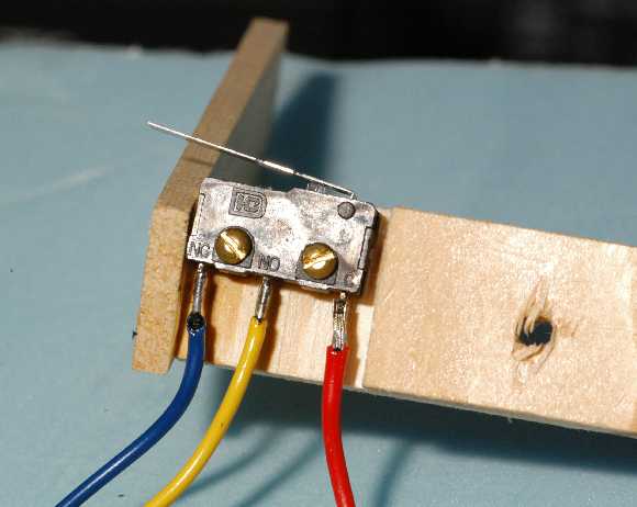
The ground throw controls the turnout. The ground throw moves the throw bar. The throw bar moves the piano wire. The piano wire operates the micro switch. This is something you can add to any layout.
You will see a rather long piece of metal with a pivot for the piano wire. You might ask, "Why???" If you think of the piano wire as it is moved by the throw bar, the piano wire moves as much as the throw bar at the top. At the bottom, it doesn't move at all. In the middle of the piano wire, it moves half as much. The micro switch needs about 1/10th of an inch (2.5mm) of movement to activate it - which is about the amount the throw bar moves. So percentage wise, it is important that the microswitch be located near the top of the piano wire. By using a long piano wire, we are in the upper 70% of the piano wire and it works well. When we first tried this, we used a block of wood that was only about 1 inch (25mm) long. It worked, but was touchy. Now we use an arm that is 3.5"(89mm) long. You might be able to experiment and find a piece of metal between 1 inch and 3.5 inches (89mm) works. If you don't want to experiment, just make yours like ours.
It consists of:
1. A 1A micro switch.
2. A piece of aluminum.
3. An L-shaped piece of piano wire.
4. Two screws to hold the bracket layout and two 2-56 screws to hold
the micro switch.
The piano wire:
The short leg of the L-shape is about 1/2" long (13mm). The long end is as long as necessary to reach through your layout and poke through a hole in your throw bar — one not used by the ground throw, of course! Most throw bars have a hole in the middle. We use that one. But you can use any spare hole in your throw bar or drill a new one. After the piano wire is inserted into the small hole of the metal bracket, the end is bent over to keep it from falling out of the bracket.
Top View: Microswitch is shown mounted in a recess. The original bracket was made of wood, but it proved to be easily broken when one reaches under the layout.
The micro switch:
The micro switch is available from www.Digikey.com. Digikey p/n is CH884-ND.
There are three terminals on the micro switch. They are usually labeled NC, NO, and COM. The COM goes to the frog. The NC and NO go to the rails, or as I prefer, the buses that feed the rails. Which one goes where? Temporarily hook them up. If a train shorts on the frog, Murphy tricked you into temporarily hooking them up wrong. Switch them. Try again. If no short, solder them. As a practical matter, we pre-solder wires to the micro switches. The other ends of the wires we hook up temporarily. You will find that if you follow a consistent mounting orientation, they can all be hooked up the same.
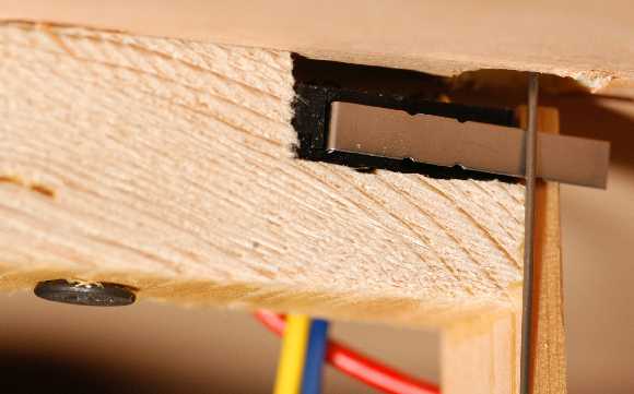
Mounting:
To mount and adjust, there are two things you can do. First, assemble everything and slide the piano wire through the throw bar. Move the piece of metal around until you can throw the turnout and hear the micro switch clicking as you do so. You can also hook up an ohm meter to between COM and either NO or NC if you cannot hear the switch clicking. When you have it working, screw it in place.
If after mounting it, you find it needs some more adjustment, you can use a pair of pliers to bend the lever on the micro switch.
Note: I should mention, this was done on HO. For smaller scales, like HOn3 and N, the piano wire movement is likely to be less. I think this approach could still be made to work, but it may be trickier. First, make sure the throw bar moves enough to operate a microswitch. Then, if need be, make the piece of metal taller and piano wire longer.
![]()
Automatic Frog Powering - Frog Juicer
The Frog Juicer is an automatic frog polarity controller. It can be used with just about any turnout that needs frog polarity control. Since virtually all the reachable turnouts on my layout are manually operated, I have over 100 Frog Juicers on my layout.
1. If you have trouble wiring frogs with the correct polarity. This product only has three wires - two to the track bus and one to the frog. There are no adjustments or CVs. You can't go wrong and will have it installed in under five minutes.
2. If your turnout is in a difficult location and hard to mount a frog polarity switch under the turnout.
3. You are using a Peco, Walthers, or similar turnout that has a spring to lock the points to the stock rails. With a turnout like this, you need no ground throw or other mechanism, but you will still need something to power route the frog.
It is called a Frog Juicer. It comes in a single frog, dual frog, and a hex (six) frog configuration. Think of it as half an auto-reverse section controller. You're in luck, it is also about half the price!
Frog Juicers have no mechanical linkages, so they fit neatly under your layout. They have no adjustments to make. If you use sprung point turnouts like the Peco Electrofrog, you won't even need a ground throw. If you take your time, it will take about 5 minutes to install one.
It works with virtually all DCC systems. It does not work with DCC systems that put out less than 1.7A because 1.7A is the frog juicer's trip point. (Such systems are the Bachmann EZ-DCC and the Sprog II.) It may be possible to add boosters to low-current systems like these.
Check out Frog Juicers at: https://www.TamValleyDepot.com You will find frog juicer manuals and wiring diagrams for the Frog Juicer to turnouts, crossings (diamonds), and double crossovers. Just think of what it would take to wire a double crossover. You will be impressed at how simple Frog Juicers make the task!
 |
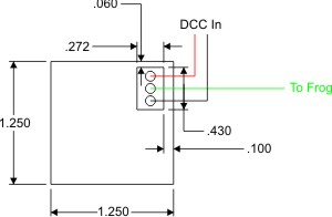 |
Single turnout Frog Juicer
If you are planning on signalling and block detection, be sure to read about using Frog Juicers with block detection in the section on Block Detection.
Which Frog Juicer should you buy? There isn't much of a price savings for a hex juicer over a mono juicer, so buy the juicer that is right for your application. For single turnouts, buy a mono juicer and put it under the turnout. If you have a crossover or crossing (diamond), use a dual juicer. For a double crossover, use a hex juicer. If you have a yard with multiple turnouts on the same DCC block, you may want to use a hex juicer here as well.
![]()
Tam Valley Depot's Kermit The #6 Frog.
Depending on what is in the glass, some frogs are happier than others!
Remember: A live frog is a happy frog! No frogs were harmed in the making of this product! Juice is electrical slang in the U.S. for electricity. A power routed frog is often referred to as a live frog.
![]()
SUGGESTION: Automatic Balloon Track Control
Use a DCC autoreverser to control the turnout leading to a balloon track. See the circuit in the section on turnout control.
![]()
SUGGESTION: How to Provide Turnout Position Indication
See the circuit in the new section on signaling.
DUAL GAUGE / NARROW GAUGE |
SUGGESTION: Wiring Dual Gauge Turnouts
Please note that I am not a dual gauge modeler. What is written here is based on examining a friend's layout that is and is wired for DCC. If you have anything that you think I should add, please write me.
Dual gauge turnouts look complicated, and mechanically they are, but wiring them is not a big deal. Due to its mechanical complexity, it is not possible to make a dual gauge turnout DCC friendly unless you scratch build it. Most of you will use a turnout, such as the Shinohara turnout shown here. It is recommended that you attach a feeder to the movable points. There are three movable points. There are two shown in green. One feeder may be used for these two points and must be attached to your power routing switch in your switch machine. There is one point shown in red that should have a feeder attached to the bus serving the outside rail. If you can't make a dual guage turnout DCC friendly, what do you do? If you are using light bulbs discussed elsewhere in this website, this will be adequate. If you are not using bulbs, you may use electronic circuit breakers such as those sold by Tony's Train Exchange, Digitrax or others. Otherwise, your booster will simply shut down. |
 |
Wiring a gauge separating turnout: I don't know what this thing is really called. It is a track work arrangement that separates a dual gauge track into a standard gauge track and a narrow gauge track. It has no moving points. The guard rail guides the flange of a standard gauge train to the left while narrow gauge trains proceed straight ahead. Clever! Because there are no moving parts, this presents somewhat of a dilemma for the modeler. How do you power route the frog? It would be nice if this can be done automatically. Fortunately, this can be done using a 4-wire auto reverse unit Better yet, use a Mono Frog Juicer from Fast Tracks. This is an automatic frog polarity controller that does not need microswitches. It's a three wire device and only costs $13.99 - about half the price of a typical 4-wire auto reversing unit. Check it out at https://www.handlaidtrack.com/Mono-Frog-Juicer-Automatic-Frog-Polarity-Switcher-p/mfj001.htm A 4-wire auto reverse unit typically has two wires going to a bus and two wires to a single reversing zone. This type of reversing unit is distinguished from auto reverse units that require triggering zones such as the Loy's Toys ARSC. Loy's ARSC cannot be used with this type of turnout. Some auto reverse units have more than one auto reverse unit on one circuit board. Such is the Digitrax PM-42. On a per circuit basis, each circuit equates to a 4-wire auto reverse unit. The main, distinguishing feature of a 4-wire auto reverse unit is that it does not require separate triggering zones. |
 |
You will notice that one of the outputs of the 4-wire reverser is not connected. It is therefore important that the 4-wire reverser that you are using must be able to trigger itself when it senses a short on a single rail only. The easiest thing to do is to hook it up as shown above and try it. You won't damage anything if it doesn't work. If you can alternate between a narrow gauge and standard gauge locomotive with no problem, then you are good to go. If it does not work, try using the other output. If neither output works, then you will need to use another brand of auto reverser.
Here is a partial list of those auto reversers that are believed to work:
Lenz LK 100 (relay type) - buy at Tony's
Train Exchange
DCC Specialties OnGuard-AR (electronic type) - buy at Tony's
Train Exchange
Many others are expected to work. We just haven't tried them. If you know that another type will work, please write me.
If you have not bought an auto reverser yet and want to try it in the store before you buy it, Mark Guirries suggests the following test:
The goal of this test is to determine the products suitability for single rail short detection and proper correction. If the booster never shutdowns because of short detected during the test, then the Autoreverser (called AR) ad passes that test. If the device passes all 4 tests, it will be acceptable.
With an AR device inputs connected to a booster.
1) Verify the booster is working by momentarily shorting the booster output and noting its response to a short. This response is what will be used to determine pass or fail for the next test.
2) Pick only one of the AR output wires and touch it to one of the AR input wires and note the booster's response.
3) Using the same output wire, touch it to the OTHER AR input wire and again note the booster's response.
4) Repeat test 2 and 3 again but using the OTHER AR OUTPUT wire and again note the response.
It should be noted that if an AR device works successfully with only ONE of the two output wires but fails the other wire test, it still can be used provided you use the output wire that works!
Observation: The performance of electronic AR solutions, no relays
involved, will potentially be much better in terms of response time.
From an operations point of view, you can often see the difference
in
the headlight. You often get a "blink" with a relay solution
and none
with electronic. At worse with a relay solution the engine jerks it
way
through depending on the existence or size of a flywheel. This is due
to
the relay's mechanical mass which creates a small delay in the response
time to the correct polarity.
For more on dual gauge track wiring, see the section on wiring track.
MISCELLANEOUS
|
![]()
SUGGESTION #2-11: Making Circuit Board Throw Bars.
With the right tools, they are easy. Without them, it is more than difficult. It's impossible! Before deciding to make any, seriously consider buying them! See the section above, 2-19.
 Some of the operations
can be done with a table saw, radial arm saw, joiner, or router. If
you invested in these tools, then I will assume that you invested
the time to learn how to operate them safely. You must read
the owner's manual that came with it; particularly the sections on
safety. You must also know what hazards exist when using the
tool and under what conditions the tool will kick or pull. Your
fingers may be very close to the work where any mishap will almost
certainly result in a loss of fingers or worse. If you choose
to use an unguarded table saw, you must know the hazards of doing
so. If you do not consider yourself an expert on the tool you
own, have a friend who is give you some pointers. Maybe they
will even do the work for you! While I own a few of these tools,
I use them only to build the bench work for my railroad and do not
consider myself an expert on using them by any means.
Some of the operations
can be done with a table saw, radial arm saw, joiner, or router. If
you invested in these tools, then I will assume that you invested
the time to learn how to operate them safely. You must read
the owner's manual that came with it; particularly the sections on
safety. You must also know what hazards exist when using the
tool and under what conditions the tool will kick or pull. Your
fingers may be very close to the work where any mishap will almost
certainly result in a loss of fingers or worse. If you choose
to use an unguarded table saw, you must know the hazards of doing
so. If you do not consider yourself an expert on the tool you
own, have a friend who is give you some pointers. Maybe they
will even do the work for you! While I own a few of these tools,
I use them only to build the bench work for my railroad and do not
consider myself an expert on using them by any means.
Radial arm saws can pull things, like fingers and arms, under the blade. Also, the blade can bite into the work and drive the saw towards you. I use my radial arm saw plugged into a power strip with a 15A breaker. If the saw bites too hard and wants to travel towards me, it usually binds enough to trip the breaker before the saw unpleasantly surprises me. To avoid the saw moving towards you on its own, pull the saw towards you slowly. Keep the muscles in your arm "tensed up." NEVER, EVER, have any part of your body anywhere near the path of a radial arm saw.
Always wear safety goggles when using saws, routers, joiners - any power tool!
Small work pieces on a table saw are often kicked towards the operator. Be prepared for this. Wear a denim shop apron or other thick clothing. (I hang a tarp between my "wood shop" and cars. It keeps them from getting covered with saw dust and avoids flying pieces from nicking the paint.) Do not have your face in line with the blade and keep the saw's guard on.
When setting up your work behind the blade of a radial arm saw or anywhere near the blade of a table saw, remove the key from your saw (if it has one) or unplug it.
If you should use a shear (a guillotine for metal) at a friend's sheet metal shop, know that this tool is designed to chop things off effortlessly — things that are many more times more difficult to chop than fingers or arms. Therefore, always double check that you are clear of the blade before operating it. Otherwise, it will cut off a body part in an instant.
W. Kleinert reports "I have found that a 21tpi sabresaw blade chucked up in my old delta scrollsaw cut pc board just fine with minimal hazards. Simply use good powertool safety methods and one should have good results."
Now that we have safety covered, you need to do two things to make your own circuit boards throw bars: cut a groove down the middle of the throw bar and cut the throw bars themselves.
There are basically only two kinds of things you can use to cut circuit boards: abrasive discs and carbide tipped blades. Non-carbide tipped blades chip away at the board leaving jagged edges. Also, after I had once hacked away at 45 inches (1.1m) worth of circuit board, I found that I had no teeth left on the blade when it stopped! So this eliminates the possibility of using a jig saw or the ever popular chain saw. Carbide, on the other hand, cuts smoothly. I have not cut enough boards yet to notice any degradation of the teeth.
If you do not yet own a carbide blade, here is the excuse you were looking for to buy one. The laser cut ones with the anti-resonant S-shaped slots in them make a smooth cut on wood.
Cutting the groove:
The easiest way to do this is use you motor tool with an abrasive disc. You can also use a carbide tipped saw blade. If using a table saw, attach the circuit board securely to the bottom side of a piece of wood with double faced carpet tape. This way you can have something that allows you to keep your hands away from the blade.
A router with a carbide tipped blade should do the job nicely.
Cutting out the throw bars:
I made my circuit board throw bar just under 4/64" (1.5mm) wide. I used a Dremel stone tip to take the rough edges off the circuit board.
The best way to cut them out is with a shear. These range from small hand powered devices specifically intended for cutting circuit boards up to hydraulically powered monsters for cutting metal plates. It is wise to think of a shear as a guillotine and keep your hands away from the blade. Even the foot operated ones will chop off body parts you were not keeping a close eye on. Unfortunately, using one much bigger than a table top model is too big. Something needs to clamp the circuit board so you can keep your fingers away. The bigger shears have ways to clamp things, but they are intended for things bigger than a circuit board.
Forget using a table saw. It cut the circuit board into 1.6" (40mm) wide strips fine, but I could not cut them into little throw bars without it kicking. After the second time, I quit before I lost any fingers. Be aware that when the final cut is made on small parts, the saw will kick the strip towards you. Be wearing the appropriate protection mentioned above.
If anything, the small hobbyist table saws are probably safer to use. You will need a "zero clearance throat plate" to keep your circuit board pieces from disappearing into the saw.
Once you have your throw bar, you can cut it to the desired length easily with medium or large diagonal wire cutters.
Using Radio Shack blank circuit boards:
If you are using Radio Shack bare circuit board, it is photosensitive. It can be used with lithographic negatives to lay out fancy circuits when exposed to sunlight and then etched in acid. The only thing you need to worry about is that the board is coated with something you cannot solder to. Lightly sand it with 150 grit or higher sandpaper to remove the photosensitive layer until it shines.
![]()
INFORMATION #2-21: Other Turnouts Not Otherwise Covered
Three-Way: I have studied this turnout and was preparing a diagram for it. But in the process of deciding what had to be done to make it a DCC friendly turnout, I decided the difficulty level of surgery required by the average modeler was too great. I do not want this website to be for expert solder technicians only. This website is for average modelers. Therefore, I deem this type of turnout not practical for conversion to DCC friendliness.
A lot of modelers find this type of turnout a source of derailments and therefore, their use should be avoided. Many clubs and modelers forbid their use like the double-slip.
However, if you find that you must use them, use some sort of short circuit protection or a bulb.
N & Z: If you are capable of doing the fine soldering, go for it. These may be too difficult for the average modeler. Use some sort of short circuit protection or a bulb.
O: Two-wire O should be just like HO. I just do not have the turnouts to draw or make specific references to. Three-wire is difficult for me to say anything about them in general without seeing the turnouts.
G: Outside, you have the weather, dirt, and bugs to cause you problems. Therefore, I used a #6 turnout with an insulated frog so that I don't have to power route anything. Yes, I occasionally have trouble with my high-railer stalling, but otherwise this approach works well.
Dual Gauge — Narrow and Standard: I do not have any to study in detail. I suspect, like the three-way, one of each will need to be sacrificed to determine its exact electrical construction. Turnouts using the points to provide continuity or have a solid metal connection across the points make it difficult to ohm out the turnout without taking it apart — perhaps beyond the point of returning it to use. Certainly, any turnout I have to dismantle eliminates those that I can look at on the store shelf.
Crossovers: I have partially thought through these. There turns out to be about four variations on this. Two of them are for G-scale. They depend on the angle, a track plan that would be used for G, but probably not for a serious indoor railroad, and the fact that G can use insulated frogs. The crossovers I was thinking about would be scratch built. There are some commercial G crossovers, but so far, no one has asked about them. So I have not bothered to worry any further about these.
In HO, you have two situations. Those with the solid metal cast frogs and those without. I have one without the cast frogs and we are seeing what we think of it.
A crossing made with the solid metal frogs I really need to see. I have been asked about these. Without seeing one, I am not able to recommend anything. I am not sure that my mental picture of how one of these is put together is accurate or not.
The solid metal frog I understand looks good. There is definitely interest in it and I have heard some recommendations on how to handle them. Some of the advice on the web is a bit involved — more for the electrically inclined than the average model railroader. I think this is too complicated and think I can come up with something simpler, if not cheaper, for the average modeler to implement. But I'll need to see one of these things first.
GENERAL
|
|
DCC
FRIENDLY |
|
NEEDS
SOME WORK TO BE DCC FRIENDLY |
|
SPECIFIC
SUGGESTIONS |
|
Newbie
Notes |
|
|
Confused by terms used to refer to turnouts and frogs? Below are some helpful defnitions. I have included every name I have ever heard regarding frogs, but understand that there are really only two general types of frogs - live or electrified and dead or insulated. Electrofrog: Trademark term belonging to Peco. Modelers frequently use this term to also refer to live or electrified frogs. See electrified frog. Insulfrog: Trademark term belonging to Peco. Modelers frequently use this term to also refer to dead, insulated, or unconnected isolated frogs. See insulated frog. Dead frog: 1. See insulated frog. 2. A green frog that has been run over by a car. See green frog. Do not see live frog. Electrified frog: This is a metal frog that is wired in such a way that it can supply power to the wheels of the train rolling over it. Usually power is supplied to the frog by a general technique known as power routing. See power routed frog. Green frog: 1. An amphibious animal that eats bugs. 2. Green Frog Productions produces railfan videos. www.greenfrog.com. "Ribbit" Insulated frog: Usually plastic, but may also be pieces of rail that are not electrically connected to anything. Does not provide any electrical power to train. Isolated frog: This is a metal frog that is not electrically attached to anything. The metal frog on Atlas turnouts is a good example. Isolated frogs can be wired up to be power-routed making it an electrified or live frog. Power routed frog: Any electrified, live, or Electrofrog that is wired to some sort of switch or switching mechanism that provides power to train wheels through the frog. The switching mechanism makes sure that the power delivered to the frog is of the right polarity. Failure to use a switching mechanism or hooking it up backwards will cause a short. |
Copyright by Allan Gartner 1996 - 2019 © All rights reserved. You may print this for your own, personal, non-commercial use. Non-commercial, non-personal reproduction may be requested by visiting www.WiringForDCC.com/writeme.htm . All users, commercial and non-commercial, may link only to this site at www.WiringForDCC.com. Thanks to all who contribute to this site and the Q&A forum! |