|
Elite/Pilz/Tillig Turnouts SUGGESTION #2-13: Elite Turnouts are Ready in Just a Few Snips. Code 83
This turnout is not well suited to club or home layouts that have people that help build the layout. The throwbar and the points connections to the throwbar are easily broken. People need to treat these turnouts carefully. It seems that if the cost of the turnout is not coming out of the installer's pocket, the installer does not seem capable of treating this switch carefully and many will be broken.
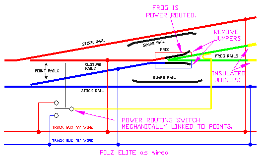
 These pre-weathered code 83 turnouts are offered straight: #4, #5, #7; curved: 15/30, 17/29, 20/32, 29/41; wye: 7.5/7.5, 6/6; single and double slip. As a nice little bonus, the point and closure rails are one piece. This eliminates the need for ever adding jumpers (called bonds) to power the points. Weathered flex track, weathered joiners, and weathered insulated joiners (yes, you read that right) are also available. Available from Reynauld's Euro Imports www.Reynaulds.com This turnout is similar to a Peco Electrofrog in that it comes as a power routing turnout. Fortunately the guard rails for the frog are plastic so you do not need to cut them like I described for the Peco Electrofrog. However, the closure rails get close to one another and metal wheels will frequently short. We have had to apply clear fingernail polish to the inside edge of the rail where they get close. Alternately, you can cut the closure rails where they get close. You can then use them either unpowered or hook them up to frog and power route them. Make sure you ask for their literature. If you do not get their diagram, follow my notes above. How to Wire This Turnout: This section assumes you have read "How to Wire Turnouts" in the section on turnouts. 1. Remove jumpers from back of frog as shown. 2. Add jumper between stock rails and closure rails as shown. Or, for less solder joints to your track, drop feeders from each closure rail to your buses as shown in color above. 3. Connect the frog to your power routing switch or switch machine. 4. Connect your power routing switch or switch machine to your bus as shown in the above drawing. If the locomotive shorts when it goes across the frog, swap the wires that connect your power routing switch or switch machine to your bus. 5. Install insulated joiners as shown. 6. Run a wire from each stock rail to the corresponding bus wire as shown in color above.
If you are having problems with shorts on your frogs: Rob England (rob_england@mail.com) has a few locomotives with fat drivers that short out on his Tillig frogs. He offers the following advice. I have been playing with these and found out that just removing the jumpers between the frog and the point/closure rails and wiring feeders to the frog and the points is not enough. Because the point and closure are one piece, the two closure rails are too close together at the frog end for DCC. Fat loco drivers (of which I have a few) short across them entering or leaving the frog. What I do is leave the manufacturer's jumpers in place. I solder a feeder wire from the frog/closure jumpers before laying the turnout. After laying the turnout, I cut the point/closure rails about three ties away from the frog with a cutting disk in a power tool. This leaves enough chairs to hold the rails in place each side of the cut. I insert into the cut a bit of the dark plastic that Tillig use to space apart their flex-track ties. I CA glue it in place, and trim it flush once the glue sets. Since Tillig turnouts are made to flex, it is better to do this cutting and gluing after you have laid them. The spacer plastic does not work with a file easily - better to trim it with an Xacto. Also I drop a bit of CA on the chairs holding any short bits of rail such as the ones I just cut and the frog rails, and the guard rails. I find the Tillig chairs are pretty low-friction plastic and the rails move easily. A bit of CA keeps things together. Since Tillig turnouts are made to flex, do this gluing after you have laid them. (I'm also considering soldering all the Tillig frogs. Just waiting to see how reliable they are as is). Finally I file the underside of the rail on the stock
rail and the point rail a couple of ties down from the cuts I made,
with a jeweler's file, then apply an 80watt soldering bolt and quickly
tin the underside with some solder. Since the Tillig track comes pre-weathered,
it is essential to file it clean for any soldering. I have found that
with a bit of filing and pre-tinning with fluxed solder, I can solder
hidden feeders to the underside of the rails no worries. In this case
I pre-tin about a cm of wire and slip it under the stock rail and the
point rail to link the two together directly, no more jumper or feeder
wires required. The wire is just below the tie tops, so paint it to
match your ballast. If it really bugs you, bend it down in a bow before
soldering it in place so it will be covered by ballast. |
|
Copyright by Allan Gartner 1996 - 2017 © All rights reserved. You may print this for your own, personal, non-commercial use. Non-commercial, non-personal reproduction may be requested by visiting www.WiringForDCC.com/writeme.htm. All users, commercial and non-commercial, may link only to this site at www.WiringForDCC.com. Thanks to all who contribute to this site and the Q&A forum! |