
|
||||
|
Click on the above to visit our featured advertisers. Tell them you saw their ad on Wiring for DCC!
My new DCC book! Track Wiring This is Part I. Go to Part II.
Please read this introduction! There have been significant changes to this particular web page! There are several sections in this website that you should read regarding track wiring. This section on track wiring, Part I, covers general wiring information, testing, and troubleshooting. Part II contains the actual wiring of track. The menu to the right will automatically take you to the right section. Connecting your track to your booster is covered in Booster
Network Wiring. Wiring your turnouts also
has its own section. Be sure to become familiar with all these sections.
They have recently been expanded to cover topics that are frequently
asked on the DCC
Q&A forum. Finally, you may find the section
on track and wire resistance interesting.
Wire Selection Forget getting wire made of different types of metal. Whether it be conductivity, cost, or flexibility (not brittle), wire is only made of one metal, copper. There are a few varitions to know about. "Oxygen-free" wire was marketed to audiophiles. I'm audiophile, but I still had my doubts about this so-called wire. I couldn't hear any difference and in a couple of years it was green. So much for being oxygen-free. Don't waste your money on this type of wire. Sometimes you can get tin-plated copper wire. This is fine. The tin prevents the copper from oxidizing. If you buy your wire and in a few months, maybe even up to a year or so, you use up the roll of wire you bought, you don't need to worry about buying tin-plated copper wire. This is because once you solder it to your track or make a firm electrical connection that keeps the air out, the connection won't oxidize. If you want tin-plated wire, it may cost a little more than non-plated copper wire, but it should not be too bad. Note: If you are wondering if a wire is tin plated, snip off an end and look at it with a magnifying glass. The center should be copper colored. Whether you buy stranded or solid wire is really a matter of personal choice. I like solid for feeders. It maintains is shape while your form it and then solder it to your rail. Also, for a given wire gauge, solid is smaller in diameter. So if you don't want feeders that are any more visible than necessary and you solder to the side of the rail, use solid. If you still want to use stranded, go right ahead. For buses, the choice is yours and depends on how you intend to connect to it. I use terminal strips to anchor my wire ends. So I use stranded house wire and solder on a spade lug to it. Do whatever works for you. Wire insulation can be bought in several different materials. This can really jack up the price - ten times or more! More expensive wire insulation is often fire resistant. This sounds great until you look at the price. If you use electronic circuit breakers and adequately size your layout wiring and turn off your DCC system when not in use, the extra money spent on fire resistant insulation may not be necessary as your wiring is unlikely to catch fire. Keep in mind that the insulation your home's wiring isn't any more fire resistance than typical wire used on model railroads and your home's frame is wood. Businesses and industries put wire in conduit, the walls may use metal studs or concrete and use fire resistant wire. If your layout is up and running the whole time museum is open, you may be required to use fire resistant wire. One last thing, teflon and other fire resistant wire may require the use of a thermal wire stripper to remove the jacket. New one of these cost about $500.
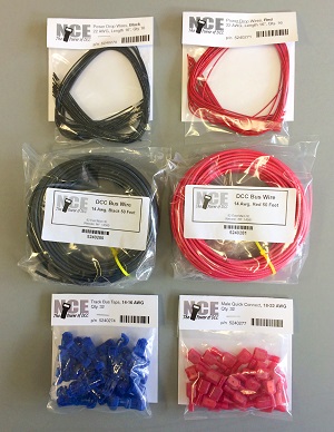
If you want to buy your wire and connectors from your favorite NCE dealer, NCE is selling wiring kits in 25, 50, and 100 foot lengths. It can be used with any DCC system. The kits include bus wires, pre-stripped 16" long feeders, and t-tap connectors for the bus wires. For example, the 25 foot kit contains 10 sets of feeders and t-taps. Also included are quick disconnects for the t-taps. This allows you to easily disconnect a bus connection should you be trouble-shooting a problem. Note! I highly recommend that you be testing for shorts as you wire your layout! Be sure to flip your turnouts as you do this. If you are wiring a yard with a lot of bus feeders, you can buy additional t-taps and wire from NCE. Check out their online store under Layout Wiring. SUGGESTION: Buy Several Boxes of Different Colored Push Pins. These are cheap, sanity saving devices. Use one color to mark rail "A". Use another color to indicate that a section of track has been wired. Use another to indicate a problem rail switch to the track gang.
Use a 3156 or 1156 Automotive Taillight Bulb to Limit Current to a Track Sub Bus. The 1156 taillight bulb has been around for years, but it is starting to get scarce. The new version of the 1156 is the 3156. The science is the same for both bulbs, so read what I have below. Then I wrote about the 3156 and using it. Also, before I get into taillight bulbs, I write about the increasingly popular LED. Incadescent tail light bulbs may become hard to find. Also, you might like something that takes up less space. Check out these space-saving alternatives. Can You Use an LED Instead of a Bulb? Unfortunately not. A light bulb works because its resistance increases when it heats up and lights. This increased resistance is how a light bulb limits a short. The resistance of an LED does not increase when it heats up. So it won't work. If you are tempted to try it anyway, you will find that the LED will not allow your locomotive to properly receive the DCC signal and power. Your locomotive will not run properly. Furthermore, if you have a short, your LED will burn out very quickly. Should You Use Taillight Bulbs, Circuit Breakers, or Neither??? The use of light bulbs to limit current has been occurring long before I was born. Heck, even the use of car taillight bulbs in model trains wasn't my idea. Since the bulbs I saw in an old Model Railroader were all obsolete, I ran tests and determined that the very low cost #1156 was the optimal choice. Other than publishing my findings here in my web page, I would have expected this to be the extent of my contribution to the hobby on this topic. Instead, I've not only evidently sold tons of bulbs — with not a bit of thanks from the bulb manufacturers! — but the topic continues to generate a ton of email on the Internet. Since the topic is still not clearly understood by all, I thought I'd come back and rewrite things and try to do a better job by adding a few things that have been learned over the past few years. Why use taillight bulbs? A taillight bulb is a low cost way to limit current when a short occurs on your layout. Shorts typically occur when a train derails or when points and wheel sets are out of tolerance and touch. When bulbs are used to supply power to a sub bus, only that sub bus will be affected. The train(s) in that sub bus will stop. Any other trains attached to that same booster will not. As an extra bonus, the bright light provides quick localization to a short — it lights up your feet! Why use bulbs? Why do they work regarding shorts? A light bulb is cheap and seemingly simple. Why use them to limit current in shorts? What makes them work? A light bulb when it is off and cool has a very low resistance. If this was all there was to a light bulb, it would be useless in protecting shorts. However, its very low resistance allows the train to receive nearly full voltage and current. So when there is no short it is as if the bulb was nothing more than a piece of wire. When a short occurs, a much higher amount of current attempts to flow to your track. This much higher current causes the light bulb to light. This is where the important thing happens. The bulb is very hot when lit. The wire inside bulb has what is known as a positive temperature coefficient. When the temperature goes up so does the resistance of the bulb. The resistance of the bulb now has a much higher resistance than when it was cold. This higher resistance limits the current to the short. When the short goes away, the current flowing through the bulb drops off. The bulb cools. It goes back to having a very low resistance and your train runs again. It is not the intent of this website to talk you out of buying circuit breakers. Since the bulbs are much less expensive than electronic circuit breakers, you can afford to have more of them. This allows you to sub divide your layout into smaller electrical pieces in an effort to more quickly localize a short when one occurs. This is why I and others use bulbs instead of circuit breakers. It's a choice you have and thought you might like to know about it! Taillight bulbs do not make shorts go away. If a short takes place, you will have to resolve it right then and there — just as you would if you didn't use them. The same goes for circuit breakers. I must warn you, however. There will still be a lot of current flowing through the short, as well as all the wires and trackwork leading up to the short. Enough heat can be generated to melt ties and do some minor welding. The group I am associated with has wooden ties. We haven't had any side effects like welding or melting, but I understand that it has happened to some people, so I felt you should be fairly warned. So you may want to put a switch in series with the bulb. As soon as a short develops, you can hit the switch. I personally don't bother with switches. If I'm worried about melting, burning, or damaging anything I would hit the master kill on my DCC throttle. You will rarely feel the need to do this. Do you have to use taillight bulbs or circuit breakers? Positively, absolutely, not. The use of either the bulb or the circuit breaker is simply to subdivide a layout into smaller electrical pieces for easier troubleshooting. Also, when a short triggers either of these devices, only trains in that smaller electrical section are affected. Not using either of these devices simply means a bigger portion of your layout will shut down when a short takes place. This is hardly a catastrophe. So why did I ever bother looking into taillight bulbs? Before command control of any kind, not just DCC, derailments took place, but they only affected one train, one operator, and one power pack. No one thought anything of it. This is how it had always been since my first train set! But when a club I was in went DCC, every short shut down the entire layout. (The DCC system we were using at the time compounded the problem by sending a shutdown command to all boosters, whether that booster was truly affected or not.) Three or four shorts an operating session per each of the fifteen or so operators meant the entire layout was shutting down an average of every three minutes. People were rapidly getting disgusted with DCC! With ancient, inconsistent, undocumented, and in some cases, incorrect wiring, as well as turnouts and things that weren't in gauge any more, finding the source of the shutdown never had us shutdown less than five minutes and usually more like fifteen. Without electronic circuit breakers available at the time and the bank already broken outfitting the large layout with DCC, I went after the age old solution of taillight bulbs before a posse went and lynched the DCC equipment manufacturer. A few years later I joined a club that had just gone with a non-DCC command control. History repeated itself. Now a veteran of the taillight, I showed up the next week with a fist full of fixes. Should you use taillight bulbs or circuit breakers? This is perhaps the most important question you need to answer for yourself. The more boosters you can afford to have, resulting in a layout that is broken up into smaller electrical sections (known as booster districts), the less you will have a need for either bulbs or circuit breakers. The fewer operators and trains you have, the less likely an aggravating short will take place. The more perfect your trackwork, turnouts, rolling stock, and locomotives are in, the less likely you will have a short. Now if you could only keep momentarily inattentive operators from trying to run through a turnout thrown against them! The majority of shorts occur at turnouts. Avoid minor welding, melting ties, and lighting that bulb, or tripping the circuit breaker or booster; use DCC friendly turnouts if you can. The use of DCC friendly turnouts, discussed in the turnout section of this web page, is not required. It is simply another choice you have as a modeler. The clubs I have been in and their members have come to love the bulbs. Members building layouts at home are building the bulbs in from the start. They like the ease of troubleshooting the bulbs provide and they really like the floor lighting up in the vicinity of the problem. The choice of either or neither is completely yours. This web page simply wants you to know your choices. Can you add them later? Yes. If you think you might, then seriously consider putting in sub buses now. This is especially true if you might use bulbs. If you don't, it will definitely be much more difficult, but not impossible, to add breakers or bulbs later. How long your sub buses are, is not nearly as important as installing them in the first place. You will have to add sub buses in some way to use bulbs. You can always cut sub buses in half. Especially if you want to use bulbs, where very short sub buses are part of the attraction to using bulbs, look at the layout wiring diagrams in this web page to understand the usage of sub buses. Do taillight bulbs always work? No. Most manufacturers of modern boosters will shut down before the taillight will activate. Fast Acting Boosters: Lighted Passenger Trains: Boosters That Are Running Within About 2-3 Amps of
Their Rated Capacity: Working On The Various Scales: G scale: Do not use bulbs for G scale. You probably don't have so many trains and operators that this would be an issue for you anyway. O and S: Bulbs will probably only work with O and S scale locomotives with high quality motors. HO: Of course! If you have double headed trains, you shouldn't have trouble using bulbs. Triple or more may light the bulb. High quality locos, low or no grade, and more locos than cars :) may work fine. N, Z: You can probably lash five locomotives together. One word of caution when using bulbs for these smaller scales. As noted earlier, bulbs do not cut stop the short, they merely limit the amount of current below the trip threshold of the boosters. But these currents are still fairly high for the small components in these smaller scales. Melted or otherwise damaged parts are entirely possible. The operating environments that N and particular Z are used in may not even make bulbs an appealing option to be considered. Can you use taillights and circuit breakers? Probably not. You probably wouldn't want to anyway. They both serve the same goal — to limit the amount of a layout affected when a short occurs. Should you use sockets with these bulbs? The cheapest socket I could find for these bulbs was $4. Tail light bulbs are designed to go on and off a zillion times. If you used DCC friendly turnouts and laid your track well, hopefully these bulbs will light infrequently and last a lifetime. I received an email saying someone installed them in the 50's on his layout and has yet to burn one out. One reason to use a socket is if you plan to use the bulb as a switch - that is, if you plan to remove the bulb to isolate a section of track. A switch and the socket are essentially the same price so go for it. Since I use micro switches with Switchmaster turnout machines and slide on lugs for the micro switch, I can just slide the lug off the micro switch to act as a switch. See below for the 3156 tailight bulb. If you want to buy a socket for the 1156, one of my readers found an inexpensive socket. See See the section on Getting Electronic Parts. Reader Ed Collins makes his bulb mounts as follows: He just took a standard #6 spade. Took a punch and opened up the slot on the end you solder the wire in. Flattened it out, drilled a small hole large enough to get the pin on the side of the 1156 bulb into it. Solder the spade on the side of the bulb. Works fine and you do not have to try and buy a special connector. Digitrax Chief Owners: You will have to set the Chief option #18 to 'closed.' This causes the DCS100 to delay for 1/2 second before reacting to a short circuit, rather than the 1/8 second it comes set to from the factory. If you came here from the section on wiring turnouts, click here to return to wiring turnouts. Are They Hard to Find? This bulb isn't as popular in cars as it used to be. While you can still get them at auto supply stores and discount stores automotive departments, you may want to try D. Erwin's suggestion. He tells me https://www.sunraylighting.com will sell in bulk and at wholesale.
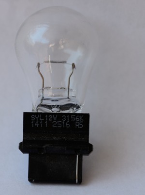
The 3156 is the modern version of the 1156. As you can see from the photo, the 3156 uses a plastic base instead of a metal one. On the right side of the photo, you can see that the 3156 has a wire termination. There is another wire on the other side.
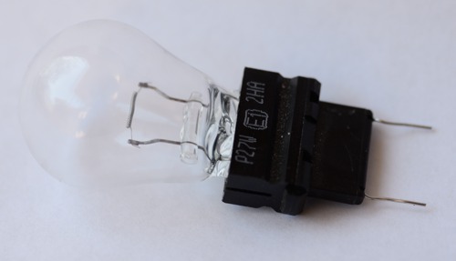
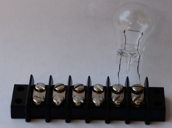
You can bend these terminations and remove the plastic base. You will need to pull firmly to remove the plastic base. Keep pulling. It will come free. You can then slide the terminations under the screw of a terminal strip. That's good because the metal blade (the "3/4 W solder terminal series 140") that I used on the 1156's is now obsolete and no longer available. And of course, you don't have to spend any additonal money for mounting the 3156. You may need to trim the leads a little bit before securing them to a terminal strip.
Alternatives to Car Tail Light Bulbs Tail light bulbs are a low cost way of limiting short circuit currents. As car manufacturers embrace LED technology, incadescent tail light bulbs will become increasingly difficult to find. Tail light bulbs have another big disadvantage with big being the operative word. They are big and take up a lot of space under a layout. So if you want an alternative to tail light bulbs, these products may interest you. Be sure to read the section above on tail light bulbs as the same pros and cons exist. For example, they only work with systems that react slowly (about a half-second) to shorts and do not interrupt the current flow completely like electronic circuit breakers. Due to slower reaction time of these devices, they may not work with all systems. Some systems have configurable reaction times. So you may have to select the extended or longer reaction times. Consult your system's manual. I suggest you buy one of these devices and try it out before you buy however many you will need.
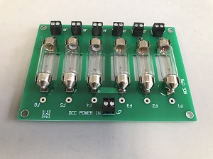
NCE CP6 It's hard to beat the simplicity of a light bulb for current limiting. The CP6 from NCE has six, 1A lamps that take up considerably less space than six tail light bulbs. This device can limit current for six zones on your layout. The lamps can be ganged together for higher current trip points for a particular zone. NCE sells spare bulbs for the CP6. Note that there is a hole in the circuit board under each lamp. You could mount the CP6 to a piece of clear or smoked plastic allowing you to see the illuminated lamp from underneath or behind the circuit board when a short occurs.
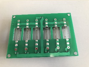
Back of CP6 showing that one of the track bus connections simply passes through from the input (top) to the output (bottom 6). The CP6 provides terminals for both wires of your track bus. One of them simply passes through. This means that you don't need to run both bus wires to the CP6 if you don't want to.
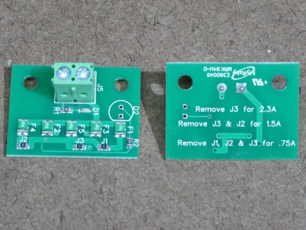
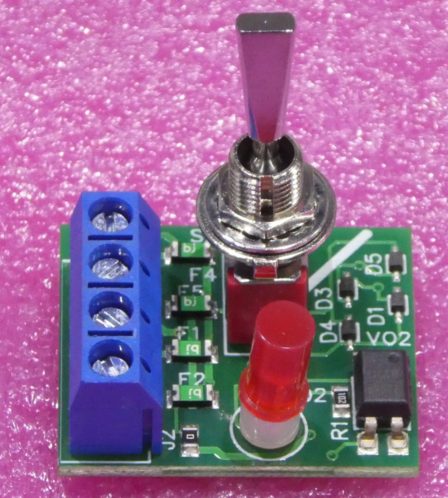
Under layout fuse (left and center) and facia mount fuse (right). The Automatic Fuse from Voltscooter Electronics www.Voltscooter.com is based on polyfuse technology and takes up less space than a tail light bulb. Polyfuses react slowly like light bulbs, but they do not light up, so I recommend adding the optional LED so that you know if the device has activated. You can put the LED directly on the device or on your indicator panel. The Automatic Fuse is configurable for several different trip currents. You do this by removing jumpers that are soldered to the board. I had trouble getting both sides of the jumper hot enough to remove, so I found it easier to snip off the jumper with some diagonal cutters. Definitely get one working the way you want it to before you go snipping away like crazy on many units. I found a discrepancy between the labeling on the back of the Fuse and the instruction sheet. The manufacturer replied with this clarification: The packaging is more accurate for steady load conditions. The other numbers are the actual fuse ratings. Because they are on the same pca (printed circuit assembly) they warm up more than they would as solitary fuses and therefore trip at a lower current. Most should remove at least J2 and J3. The Fuse is available in a panel mount version (above right) with an built-in indicator and a feedback output. If you choose this device, be mindful of how long your bus wires will need to be to connect with the fuse. See my section on track feeder lengths which will provide guidance to you. The output can be connected to an alarm or provide feedback for a signalling system or computer. Since this output is optically isolated, you can connect them together without causing ground loops (which are bad thing).
SUGGESTION: Attach Your Sub Bus Feeders With Screw Terminals.If you have a short that is troublesome to find, you will be able to disconnect the feeders. Otherwise.... you will have to start cutting your carefully soldered wires. I've seen this happen more than once, I'm afraid. I prefer soldered connections, too. But here, soldering will work against your troubleshooting efforts. The following two drawing show how I like to anchor the ends of the sub buses as well as attach to the main bus. The first arrangement shows if you are using bulbs. It could be a DCC circuit breaker. The second shows the use of a block detector and a bulb. These are just ideas that you can use for seeds for your own desired arrangement. Do note that this arrangement causes the block to be fed from one end. If you are using heavy wire and short blocks, this works well. For example, my blocks are no longer than 15 feet long and I use #14 or #12 wire for sub buses. The 15 foot length is simply so I can detect a train every 15 feet. You could probably double this without any noticeable affect on your train operations. It has the physical advantage of providing a place to anchor the end of each block — no loose ends. Also, you precisely know where one block ends and the next begins.
SUGGESTION: Develop A Color Code - And Stick To It!If you have to make a trip back to your favorite home improvement store to get more wire, do it! Your sanity is at stake here! In fact, let me suggest a color code based on the fact that many of you may want to use regular house wiring. White for the "common" bus feed. Remember common bus feeds between booster districts are NOT to be connected together! Black for your main bus. Clear or green for your sub buses. See the schematics and read on for clarification. If you use the bare copper wire as part of your feeder system, be careful it doesn't contact anything that is grounded to your home wiring. Worse, beware of contacting any other voltage sources — such as the wires going to your booster power transformer that perhaps you haven't gotten around to putting in a box.
SUGGESTION: Get Your Wire From Your Favorite Home Improvement Store.This has its advantages. Probably the most important one is that if you run out, you can easily get more wire. This convenience will help you stick to your color code scheme. Also, the price may be more reasonable than any electronic supply store. At a home improvement store you can find: Heavy stranded wire. At Home Depot, they stock: 14 AWG: Blk Beige Red Blu Grn Wht 12 AWG: Blk Red(Rose) Wht Blu Org Yel Brn Grn 10 AWG: Brn Org Yel Blk Red Blu Wht Heavy solid wire for wiring homes. This stuff
is cheap, so may want to base your power distribution Light solid wire for wiring phones and thermostats. Telephone wire is the thinnest solid wire available. It only comes in 4 conductors. It could be used for your booster network where you are running a separate heavy ground. Telephone wire is red, black, yellow, and green. Thermostat wire is solid and available in 4, 6, and 8 conductors. So you may want to use this for running LocoNet and particularly the booster network. It is heavier than telephone wire, so it is less likely to break. The 4 color wire is red, green, white, and yellow. Antenna rotor (or rotator) wire is stranded. It is also available from Radio Shack. It comes in 4, 5, and 8 conductors. It is generally not color coded. Heavy duty color coded antenna rotor wire is available from amateur radio supply stores. Ask a ham radio operator where one of these is or when the next hamfest is. If you don't know a ham, don't worry about using this type of wire. While there is a lot to be said for stranded wire, if you use the brown ribbon antenna rotor variety, you may have a difficult time figuring out which edge of the ribbon is the first wire under a dimly lit layout. By the way, your local home improvement store also has
an amazingly good selection of heat shrink tubing and tie wraps.
SUGGESTION: Good Track Connection Practices Come First.Make sure you lay your track and join rails together in a manner that you think is the right way. I don't know that I really should get into this since I haven't lived long enough to see all the ways it could be done and how well they hold up. Considerations: Some people don't solder switches in place so they are easy to remove if they need any work. Some people don't like to solder too many pieces of track together due to expansion considerations. You definitely need to consider the temperature swing in your layout room. Is it in the house or out in the garage? So after deciding what your track laying practices are going to be, follow this basic rule: Every piece of track should be soldered to something. That can be another piece of track or a wire. The wire can be a feeder or a jumper from the adjacent rail. DO NOT count on a metal joiner to carry power to the next rail. It WILL let you down eventually. I expect you knew that already.
SUGGESTION: Using Insulation Displacement Connectors (IDC).An article by Tony Koester in the August 1998 Model Railroader discussed using insulation displacement connectors. These are commonly used for installing aftermarket automotive products like car alarms. Frequently they are used to clip onto existing wires for power and ground. Not surprisingly, someone might want to use them to connect to DCC power busses. An insulation displacement connector is a type of connector that has a fork with a knife edge. It can pierce a wire's insulation and make good electrical contact with the encased wire. There is no need to strip a wire and the connection can be made in a second. This type of connection has been used by phone companies for several decades. Their reliability, WHEN USED PROPERLY, has been proven. Using them properly, requires that you do these things: 1. You MUST use the proper one for the wire sizes you will be using. If you are using one that is too small for your wire, it may bite into the wire too much. It might then break. If too large, a poor or non-permanent connection may be made. 2. If you must unclamp the IDC, do not reclamp it exactly where it was previously. When clamped, it must clamp onto a fresh location. This location does not need to be far. The location of the bite need only be a fresh one. An 1/8" or 2mm is adequate. 3. Use the tool 3M makes for squeezing the IDC around the wire. Based on reader experience, this seems critical. Trying to save a few dollars and using a pair of pliers results in IDCs that fail. Do NOT tug any wire or allow any strain to be imparted onto a wire attached using an IDC. There is no way for me to say how much is too much. At one extreme, you have the telephone application, where the cabling is installed and virtually never touched. Works great. At the other extreme, you have fragile computer ribbon cables that are occasionally misapplied to save money in applications where the cable may be moved several dozen or more times. They fail. Ribbon cables inside computers generally do okay if the person is mindful of them. It is almost inevitable in the life of a layout that some tugging to troubleshoot a problem will be done. Or maybe you will need to add or remove some track necessitating the need to tug on wires. Or, in pulling new wires, they get slightly wrapped around existing wires and some strain is imparted. You may find yourself having to disconnect feeders should you have to troubleshoot shorts. Do not reattach in exactly the same place on the wires. As long as you heed my cautions, using IDCs should work well for you. With some strain inevitable, it is difficult to say if you will start having problems several years from now. These connectors are easy to install and may be ideal for someone who hasn't developed the knack for soldering. Soldering is still the best connection possible. If you don't mind soldering, then stay with soldering. If nothing else, soldering is cheaper. One advantage of terminal blocks is that they force a certain amount of neatness. They can be rigidly mounted in a fixed location (you always know where it is) and it can be labeled. A splice, IDC, solder, or any other type of "floating" connection (its location may change whenever it is tugged) has minimal labeling (wrapped around the wire) if labeled at all. The photo of the IDCs in Model Railroader show the advantage of a floating connection. It is close to where it is needed. It MIGHT not need any labeling at all. You can carry the floating connections too far. Even though it seemed like a good idea at the time you did your installation, you can easily end up with a unbelievable mess. You may have to do a lot tugging to find out where wires go to or come from. If using IDCs, lots of tugging is the last thing you want. Use terminal strips where you would have used them whether or not you used IDCs. Label your wires. Any label at all that provides unique identification of a wire is better than no label at all. Label the wire frequently so you don't have to do a lot tugging. Labels at both ends of a 20' long wire do you no good when you are in the middle! Every other joist is good. Avoid chaining. That is a IDC that is connected to a wire that is connected to an IDC that is connected to a wire.....that is connected to a bus. If you have a problem in this situation, it could be difficult to troubleshoot. Hold yourself to two IDCs or less between ANY track feed and a booster. Also make sure your buses are continuous pieces of wire, mechanically well connected at joints, like well twisted and soldered, or use terminal strips. If using lugs on terminal strips, solder the wire to the lug. In lugs, even if the wire doesn't pull out, tugging on the connection could ultimately lead to a poor connection. Your bus wires are your most important wires! Make sure the quality of their connection to their sources (boosters) is without question! Make sure it acts likes a continuous piece of wire and can withstand tugging. Where to buy IDCs: IDCs are common in car radio installation kits. But they are not commonly used for home wiring or anything else. So you will have a hard time finding them in any store of any kind. Modelers have tried Radio Shack, auto stores, local electrical distributors and such. Your best bet is a mail-order electrical components distributor like Mouser. You will get the quantity you need at a good price as well as a variety of choices - necessary to make sure you use the right one for your application. See the section on Getting Electronic Parts for IDC part numbers and suppliers.
Attaching Feeders to Your Track: There are many ways to attach feeders to your track. There is no really wrong way to do it. Pick the method that suits you. I'll present how I do it here. Since I don't have a lot of experience doing it other ways, I'll let you read about other people's methods on the internet. While there is no wrong way to attach feeders, there are some myths. I'll debunk those here. General feeder attachment methods: 1. Attach a solid wire to the outside of the rail web. This is the most popular method. This is the method I use. While not invisible, it is still pretty hard to see. Popular with modelers is to use the smallest wire possible. To find out what feeder size and maximum lengths you can use, see my table on this website at: wiringfordcc.com/track_2.htm#feeder_experiment I like to use 20 #AWG, but many people use 22 or 24. As long as the insulation is not above the roadbed, once you ballast your track, it is pretty hard to spot. If you weather your rail and paint the completed solder joint, it is even harder to spot.
An example of a solid feeder attached to the outside of unweathered rail. I took the picture so that if you can make the image on your screen to be about the same size as the ruler, you will get a good idea of what it would look like on your railroad. If you think you might like this, make a little test sample of ballasted track for yourself and attach a feeder. Try it under different lighting. Weather it, too, if you want to. In any event, it looks better than rail joiners! My apologies, I couldn't get a light stand behind my camera in the isle. 2. Attach a stranded wire to the outside of the rail web. Stranded wire is bigger in diameter than solid of the same wire size. While this is true, it isn't too bad if you want to attach feeders this way. But the only reason I have heard to use this approach is based on a myth. That is solid wire breaks. If you use a wire stripper set to the right wire size, breakage won't be a problem. 3. Attach a wire to the bottom of the rail. This is the most invisible method. If you are a proud, card-carrying rivot counter, this is the way to go. More modelers would do it this way if it wasn't the hardest way to attach feeders. You have to drill a small hole precisely under the spot on the rail you intend to attach the feeder - and then attach the feeder to the rail at that spot. Of all the methods, it is the hardest method to avoid melting ties. I built a module this way many years ago when I hand laid track on wooden ties - avoiding the melting tie problem - but decided this approach was not practical for me. How to attach a solid wire feeder. 1. If you rail is preweathered, I just use a Dremel with a wire brush to remove the weathering where you will be attaching your feeder. Some modelers us a pointy tool to scrape the weathering off. 2. Drill a hole next to your track. Feed your wire up through the hole. 3. Strip your wire and shape as shown. Be sure to use a wire stripper set to the size wire you are using to avoid nicking the wire. Nicked wires can break. Obviously, strip off enough insulation so that the insulation will not be visible once installed and the track is ballasted.
4. Most of the time, things will work just right and the bent wire will lay right up against the outside of the rail. If it won't stay put,and firmly against the rail, use foreceps to hold the wire against the rail. Note that you want good mechanical contact of the feeder to your track for best results when soldering. So don't be afraid to use foreceps. 5. For soldering, I have a whole section on soldering. My favorite approach is to use liquid (gel) flux from H&N Electronics applied with a toothpick. Use SOLID (without a flux core) solder. For your continued, good health, use lead-free solder also available from H&N. I prefer to use a resistance soldering station. This is also covered in the soldering section. Note that a resistance soldering station is typically used with electrofied soldering tweezers. So you won't need foreceps. My objective when soldering feeders is to heat up the joint quickly and get the job done before the heat travels far down the rail and melts ties. Again, refer to the section on soldering. 6. When done, weather your rail, if you like, and ballast your track.
RECOMMENDATION: Build a Short Detecting Beeper BEFORE You Start ANY DCC Track Wiring! It's no accident that this recommendation is the first in the track wiring section. If you wait until you find out you have shorts, it's too late. Don't wait until you wish you had made one of these. Do it now. It only takes a few minutes and a few dollars to put together.
Of course, Radio Shack is gone. You can get a buzzer from Jameco. Many buzzers will work. I selected one from Jameco that has leads and runs on a 9V battery. The Jameco part number is 2117430. Their part number for a 9V battery clip is 1949488, Then attach this instead of a booster to your track while doing all wiring. Any wiring error that you make that results in a short will cause an immediate beeeeeep. This is before you've soldered the wire or hooked up twenty feeders only to find nothing works! Use this thing religiously. If you have several boosters, you will need to move the beeper to each booster district as you wire. Alternately, if you have a team wiring several districts at once, temporarily jumper the main booster feeders together so only one beeper is needed. You could also mount the circuit in a bobber caboose or clip it to the track with alligator clips. Be sure the boosters are not connected to the track. I cannot emphasize this enough. The booster will appear as a short to the beeper. Nothing but the beeper should be attached to the track. This includes things like Frog Juicers and auto reversing controllers. These are great products, but you will need to install them last because they will all cause the buzzer to sound. You can use a light bulb instead of a buzzer. Light bulbs are a less sensitive than the buzzer. But if you use a light bulb, be constantly looking at it. You can easily be wiring happily along and not notice the light. Also note, do not use an LED if you are using Frog Juicers and electronic auto reversing controllers. Like the buzzer, and LEDs are very sensitive. If you do use LEDs, hook up the Frog Juicer and electronic auto reversing controllers last. You can use an ohmmeter, but you will get squirelly results. So don't do this unless you have a very good understanding of exactly how an ohmmeter works.
For a club, you might want the following buzzer:
It is designed to have the buzzer attached to the track
whenever the DCC is not on. This is so people don't forget to use the
buzzer. C1 is 25V or higher 1000uF capacitor. R1 ohms = (Vbooster -
Vrelay)/Irelay. R1 wattage = (Vbooster - Vrelay) x Irelay. R1 may not
be needed at all as some relays will run fine at 14V without damage.
A Simple Test Indicator Light for DCC Contributed by Don Vollrath Many times during construction or troubleshooting there will be a need to verify if there is DCC voltage between the proper track rails as expected …or not… or if the polarity is reversed across gaps in the track, or if anything on the other side of the gap is even connected. One may be tempted to use a voltmeter or an LED type tester to help perform the task. However these instruments can sometimes be too sensitive and yield confusing results, particularly where long wire or track rails are involved. The simple reason is the continuous polarity switching of DCC voltage can cause a minute amount of ‘leakage’ current to flow even when something is seemingly unconnected. This can cause a sensitive LED to glow or an AC voltmeter to read something unexpected. A more positive solution is to use a small incandescent bulb that draws significant amount of current for such testing. When an incandescent bulb needing more than 10 milli-amps (ma) is used there is no doubt that DCC voltage is or is not present between the two probed points. Either the bulb lights up or it doesn’t. You can make your own probe using a 14V, 30ma bulb such as Miniatronics #18-014-10. A convenient ready made probe type tester with a clip on lead found in automotive parts stores under the BALKAMP brand draws about 200 ma on DCC power.
SUGGESTION: Measuring DCC Track Voltage and Current (Amperage)Attention Master Model Railroaders: I have heard that measuring current is a requirement for achieving Master Model Railroad. Here's how to do it! Tony's Train Exchange makes a combination DCC ammeter and voltmeter. First, let's discuss how we should refer to the voltage we measure. This is more for those already familiar with AC voltage measurements. If you are not, skip to the next paragraph so that you can measure your DCC track voltage and current. AC is usually measured with qualifiers such as "rms", "average", "peak", and "peak-to-peak." DCC is square wave AC. What should we call it? Extreme few of us own "true-reading rms" meters, so forget rms. Only old analog meters, with a needle, read average. Peak and peak-to-peak refer to a ground reference. A decoder has no way of knowing any such reference. So do either of these have meaning to us? While technically, all these can be used to refer to DCC voltage, the only thing that really matters is what the absolute peak voltage applied across the input leads of a decoder. Many devices can be used with DCC. These often contain documentation that says "do not exceed 24 volts" or something to that effect. So what I do is convert DCC to DC, to be measured by a standard DC voltmeter, and simply refer to it as volts. Technically, "peak" would be the applicable term. Use the circuit below to convert DCC to DC and follow the directions below.
This circuit assumes that you are using a digital volt meter with an input impedance of at least 1 mega ohm.
Should you build the average or peak reading circuit? Don Vollrath has the following suggestions for you. The Average voltage detector should be used to measure and adjust the 'normal' DCC track voltage level. Use this for general track voltage measurements, anywhere on the layout, with and without track loads. Always useful to detect track voltage drops due to poor connections or poor DCC bus wiring. The Peak detector is useful to help visualize how much voltage ringing is on the system, w/o having to use a multi-K-buck oscilloscope. If the peak V is >2X the average V, one should be adding R/C suppression networks to help prevent problems. This circuit will convert DCC square wave AC to standard
DC. However, before you get excited and measuring DCC track voltage,
you need to calibrate this circuit. Here's how.
This circuit is a very slight variation on the above. It allows you to measure the amperage drawn by your DCC equipment. You could use the above circuit with the capacitor if you want to. Without the capacitor, you will get a more exact reading.
SUGGESTION: How to Know If Your Wiring is Adequate — The "Quarter Test"All manufacturers will tell you, your wiring MUST pass this test: If you short your track at any point with a coin or tool, it MUST cause your booster to shutdown. If it does not do so consistently and everywhere on your layout you try, including powered frogs, your wiring is inadequate. Melted plastic is likely and a fire is definitely possible. Your steam trains and diesels with shot rings are the only things that should be smoking on your layout — not your benchwork and wiring! If you are using light bulbs as I suggest on this website, the light should light brightly. A half lit or dim bulb is a sign of inadequate wiring. In order for this test to work, your booster must have an adequate power supply. Your booster must be supplied by a power supply that has a current rating equal to or greater than the booster's rating. If not, this test will not work. You may falsely think your booster is not working properly or your wiring is inadequate when the problem is really your power supply is too small. Do not use your old DC power pack to power your booster. It probably cannot put out enough power to operate your booster properly. See the section on booster network wiring. If shorting your bus trips your booster but shorting your track does not, you have inadequate feeders. For those who know a little bit about electricity, you may be confused by measuring the bus voltage at the feeder under the layout and reading the same thing as you measure on your track. You might be led to think they everything is good. There is a little bit more about electricity that you need to know. Voltage only drops when you have a load. If you measure the track voltage with a load - such as an operating locomotive or a car tail light bulb - you will then see the voltage drop at your track. This is a little science fair project. Once you do it, you will learn that measuring the track voltage is not a good way of testing if your wiring is adequate. In summary, let me repeat, if shorting your bus at the bus/feeder connection trips your booster but shorting your track does not, you have inadequate feeders; bad connections to your track, bus, or both; or all of the above. If you are using IDCs (insulation displacement connectors), you must be using the ones intended for the wire size you are using, they must be installed using the proper tools, and you cannot reuse them. If you soldered your wires, did you get a good solder joint? It should have a nice, smooth finish, no brown residue, and no blob. Did you solder your wires to the track and/or bus? No? That's your problem. Solder wires to your track. If not using IDCs on your buses, solder your feeders to your bus. Are you using 24 AWG wire for your feeders? They must be short and frequent. You must pass the quarter test or your wiring is inadequate.
SUGGESTION: Use a Volt Meter to Check Your Track Polarity with the Beeper. If you always use the beeper and are sure you hook it up the same way, a volt meter can help you verify that your "A" rail is really the "A" rail. Just hook up your beeper and then measure the voltage it produces with your voltmeter.
SUGGESTION: DCC Track Power Polarity Identification DCC track power is a form of AC. But it helps you keep things straight while you wire if you keep thinking of it the same way as you did with DC. You still have two wires and you need to know which is which. This is especially important topside. With your layout winding every which way, it's easy to lose track. Call them "+" and "-", "A" and "B", "Tarzan" and "Jane", whatever you like. Avoid "inside" and "outside" rail because unless you have a simple oval, chances are your inside rail will become your outside rail at some point.
Track Polarity Cars or Locomotives
Here's a great visual aid if you have trouble keeping track of which rail and wire is which or if you are troubleshooting a wiring problem. You only may need one car if you are wiring your layout. If you are troubleshooting a wiring problem, two may be useful. Paint the car any colors you want. You may find it to be a good idea to paint the car the same colors as your bus wires. You probably see where this is going. Five-finger the car around your layout and check your bus wires, if already installed, or install your bus wires as you go. Any type of car will work as well as a cheap car that normally won't stay on the track or old locomotive that isn't worth converting to DCC.
Getting Frog Polarity Correct How to quickly and easily get your frogs wired correctly. See the section on Switches.
TROUBLESHOOTING: Don't Waste Your Time Trying to Find a Short With an Ohm Meter. It never works. I really wish it did! The typical ohm meter, digital ohm meter, etc. just isn't sensitive enough. Save you energy for doing it in a way that is guaranteed to get results. That is....tip # 5-21.
TROUBLESHOOTING: Train Does Not Operate Properly When Crossing Between Booster Districts. Before you get started, be sure you are familar with what happens when trains cross between booster districts. This is covered in under reversing basics in the DCC for Beginner's section. Below is a simple way to determine if all is well with your booster wiring when a locomotive goes from one booster district to the next. All you need is a 14V-16V (for HO) light bulb. Two boosters are shown below. Note that the boosters are connected together with a ground wire. Either connect this to the ground connection on your booster, if there is one, or to the booster case if there is not. This ground wire should not be connected to the ground wire that connects to your home's wall socket (earth ground). Your boosters receive their DCC signal from a network cable that connects between all the boosters and command station. Some manufacturers have a booster built into their command station. One of the boosters can be in reversing mode. Both boosters should NEVER be in reversing mode at the same time. If they are, stop now, and make only one booster at most a reversing booster. Likewise, if you are using reversing units, the same thing applies. Follow my directions below. Don't skip steps as each step will help you identify a particular problem.
Step 1: A light bulb connected between the rails connected to booster A should light. If not, stop. One or both of the wires leading from your booster to the track is not connected to the booster. Step 2: A light bulb connected between the rails connected to booster B should light. If not, stop. You could have the same problem as in step 1.
Step 3: A light bulb connected between the red rail of booster A and the blue rail of booster B should light. If not, you may not have a good ground between the boosters or you do not have good phasing between boosters. To check phasing, swap the wires going to your track from ONE (1) of the boosters and try this step again. Step 4: A light bulb connected between the blue rail of booster A and the red rail of booster B should light. If not, you may not have a good ground between the boosters. If step 3 passes, passing this step should just be a confirmation that all is well.
Step 5: A light connected between the red rail of booster A and the red rail of booster B should NOT light. If it does, even glows a little, then either your boosters do not have a good ground between them or the boosters are putting out different voltages. If you need to measure your track's voltage, see the section above on measuring DCC. If your bulb is excessively bright or burns out in a flash, then you probably have a common rail problem. See the section on common rails in the Track Part 2 page of this website. If you have converted an existing DC layout to DCC, this is likely your problem. Step 6: A light connected between the blue rail of booster A and the blue rail of booster B should NOT light. If it does, even glows a little, then you may have the same problems as described in step 5. If you are still having problems, are you using boosters from differing manufacturers? They may not play well together. If you train changes speed as it crosses between booster districts, you may have the boosters set to different output voltages. Consult your booster's manual for instructions on how to properly set the output voltage of your boosters. In some cases, this may be as simple as flipping a switch on the front of your booster.
Verbal Short Detector Do you have a decent-sized layout with several electronic circuit breakers? Do you host operating sessions? Do you want to know right away when a track short occurs? Do you feel that LEDs aren't adequate to bring a short to your attention? While buzzers seem like a good idea, do you find it difficult to be able to tell which buzzer is going off? I have a low-cost (usually under $10), easy to implement solution for owners of DCC Specialties PSX, PSXX, PSX-AR, and PSXX-AR products. If you like buying things from eBay or Amazon, this is a project for you. Note: These instructions for adding the verbal short detector to your DCC Specialties products assume you already them hooked up to your layout and working the way you want. With the verbal short detector, you do not need their optional buzzer, but you can leave it connected if you already have the buzzer installed. Introducing the ISD 1820 Voice Module The ISD 1820 Voice Module is a complete, compact module that can store up to 10 seconds (20 seconds with modification) of a recorded message. It has a small, built-in amplifier than can drive an 8 ohm speaker. It also has a built-in microphone. It even has buttons. Just hook up 3 VDC to 3.4VDC and a speaker and you are all set to try it out. Hook up two more wires and a capacitor to your DCC Specialties product and you are in business. I've have seen prices for them vary from $1.87 each, without the speaker or cable, all the way up to $14 each. It is available on eBay and Amazon.
The ISD 1820 is just 37mm x 54mm (1.46" x 2.13"). It contains everything you need - microphone and audio amplifier too! While the application notes provide some information on extending the message length, I don't recommend doing so. For one thing, the audio quality goes down the longer you make the message. It is only telephone quality to begin with. Changing the resistor to increase the message length requires some delicate desoldering and soldering ability to the 1820 - probably beyond most modelers. Doubling the message length cuts the audio quality about 40% of what it is at 10 seconds. Have no fear, I found I can record messages like "SHORT DETECTED KNOXVILLE MARYVILLE MILEPOST 45 SHORT DETECTED KNOXVILLE MARYVILLE MILEPOST 45" with no problem in 10 seconds. I first used ISD products in the 1980's. They don't seem to be around anymore. It also appears that they may have been acquired by a Chinese company. Since I can't read Chinese, the trail goes cold. No one responded to my email. So the information I am providing here, including the application notes, is all we have to go on. In case ISD is gone for good, I have included the application notes here on my website. The ISD 1820 has been widely available from many sources on eBay, Amazon, and Aretronics.com. The price varies widely as well. You can get them for under $2, but beware, make sure you get the ones with the speaker cable
The all-important speaker cable for the ISD 1820. If you didn't get a speaker cable, I tried using DuPont cable connectors, but the pins for the speaker on the ISD 1820 are too short to make a good connection. I have found JST connectors on eBay with a 2.54mm (0.1") pitch that fit perfectly. Be careful when buying the ISD 1820 on eBay. One source, that claimed to sell the ISD 1820 with speaker, did not in fact sell the speaker and cable with it. When I contacted the seller, they had no idea what it was they were selling or what it was that I wanted. They have since removed mention of the speaker and cable from their ad. You don't need the speaker that comes with some ISD 1820's. You just need the cable. The speaker that comes with ISD 1820 is very small and inefficient. It will demonstrate that it works, but you will want a larger, more efficient speaker. With the 3.75" surplus speakers I am using, the built-in amplifier provides just enough volume to be heard in my 760 sq. ft. layout room. Trying out the ISD 1820
I've included this annotated photo of the ISD 1820. Consult the larger photo above to read the pin identifications.
Schematic of ISD 1820 Voice Module wired up to your DCC Specialties electronic circuit breaker. See table below for the appropriate terminals for the DCC Specialties product you are using. Capacitor C is 0.0047uF. Hook up your speaker to the SP1 terminals. It doesn't matter which way you hook up the two wires to the speaker. You must use an 8 ohm speaker so that you do not damage the ISD 1820. It doesn't matter how many watts the speaker is rated for as long as it is rated for at least 0.5 watts. I used a 3.75", 15 watt speaker that I bought surplus for $3.50 a few years ago. It has worked out well. Unfortunately, it doesn't seem to be available anywhere anymore. Try eBay or Parts Express. If your speaker doesn't come with an enclosure, build one for it. It will sound louder. A plastic or wooden box will do. If you have a 3.75" speaker, a box about 4"x4"x2" will be adequate. I know that a lot of modelers are not confortable soldering, so I came up with a way to minimize the amount of soldering you need to do, especially delicate soldering. So buy some DuPont cables as commonly used for Arduino projects.
DuPont cables are available on eBay in 10, 20, and 30cm lengths. 10cm is about 4" and 30cm is about 12". Buy some of each. You will use them. They easily strip apart. Shown above is a DuPont cable with female connectors on each end. These are the most common ones that I use. I bought some 3V, 2A wall warts (wall transformer) from Amazon. I cut the connector off the end and screwed it to a terminal strip. I then connected 1" pieces of stripped, 22 AWG solid wire to the terminal strip. You will slip an end from a Dupont cable over the end of the wires. The wire may bend. So use a pair of pliers close to the DuPont connector end to hold the wire while you push over the DuPont connector. Do the same for both power supply terminals. I have found that one ISD 1820 only draws about 0.25 milliamps. When talking, it only drew about 50mA. So probably only one wall wart will be all you need. So that I didn't need to worry about running very long runs of 3VDC wiring and picking up hum, I put one wall wart on each of the three peninsulas of my benchwork. Use a digital multimeter to be sure you know which terminal is the +3V terminal and which is 0V (gnd). For the +3V, connect the color of DuPont cable you choose for the +3V to either of the VCC pin on the ISD 1820. Note: Both pins to the right of VCC on the ISD 1820 are the same. Use either one. Connect the 0V DuPont cable to the ISD 1820 pin labeled GND. At this point, you should be able to press the REC button. A red LED will light. Speak into the black microphone. Hold the REC button while recording and release when done. Pres the P-E button briefly and your message will play. Rerecord if you want to change the message. Hooking Up to Your DCC Specialties PSX, PSXX, PSX-AR, or PSXX-AR The DCC Specialties products provide an optically isolated output that signals when a short is detected. The optical isolator makes it easy to use and guards against unwanted interactions or damage between your layout's other electronics. Optical isolators, like the ones in DCC Specialties' products, are intended to provide a signal to other electronics. They are usually not intended to drive LEDs unless the instructions say you can. They are definitely not intended to drive relays. They can be damaged if hooked up wrong. So pay careful attention to the table below before hooking up and turning on power to your ISD 1820. Feel free to check your documentation for your DCC Specialties product to make sure I have this right. (On my layout I have all except a PSX-AR. So I know the other three work for sure.)
DCC Specialties product terminal identification The inputs of the ISD 1820 are extremely sensitive. So the first time I tried hooking it up to my PSXX, it falsed a lot. There is nothing worse than an alarm that goes off when it is not supposed to. The solution was simple. I just added a 0.0047 uF (micro-farad) capacitor - labeled C in my schematics - across the output of the PSXX. That cured it. A 0.01uF would probably work, too, but I didn't have any of those and I had plenty of the 0.0047uF capacitors. As long as you buy one that it is rated for at least 10 volts, you are fine. 50V and 100V capacitors are very common and are just a little bigger, but plenty small enough. Side note: I have 13 of these installed. For a reason I have yet to determine, one of them falses at power up. While I hope to figure out why this one, a single false at power up is something I can live with if necessary.
The capacitor is shown on my PSX. Note I have also included two pieces of 22 AWG solid wire that I will slip the DuPont connectors onto. As I said before, be sure you hook up your DuPont connectors correctly. The collector, as shown in my table above, goes to the other VCC pin of the ISD 1820. The emitter, as shown in my table above, goes to the P-E pin of the ISD 1820. That's it! Turn your power on and short out your track. You should hear your message. What about other brands of electronic circuit breakers? The DCC Specialties brand is the only one that I know of that has an optically coupled output that indicates a short. They can probably be modified, but would require delicate soldering and modifications that must be performed correctly to avoid damage. Remember, once you start hacking apart your electronics, don't expect the product's manufacturer to help you if you ruin it. If you need more volume
TDA2030A Audio Amplifier Module. I've noticed that some do not have the screw terminals on the right. All terminals are labeled on the bottom of the circuit board. You can buy a low cost audio amplifier from eBay or Amazon for just a few dollars. It is a TDA2030A Amplifier Module. It can put out 18 watts for a few seconds into a 4 ohm speaker; 9 watts into an 8 ohm speaker when used with a 12 VDC power supply. A 2A, 12VDC wall transformer should be adequate. Since only one of your VSDs should be going off at once, this wall transformer (I like to call them wall warts) should be able to drive several TDA2030A's. Again, you can buy these from Amazon, eBay, and probably other sources. You can get them for as little as 5 for $9. Please note, while the integrated circuit on this amplifier can probably handle 18W, I have my doubts the heat sink is adequate for more than a few seconds. This will be fine for using the amplifier with the VSD, but for continuous usage, I think it will overheat.
ISD 1820 Voice Module with a TDA2030A Amplifier Module for more volume. The TDA2030A module is labeled on the bottom of its circuit board. Connect 6V to 12VDC to VCC and Gnd. Use more than 6V if you need more than a few watts of audio output. Also connect its GND to the GND on the ISD1820. Connect it's IN pin to ONE of the speaker output terminals of the ISD1820. The ISD1820 uses what is known as a differential output. So you only need to use ONE of its speaker output terminals to drive the TDS2030A. There are two green screw terminals labeled OUT and GND. Connect them to your speaker. Make sure you use a speaker that is rated for enough of the output watts you intend to use. Make sure you initially set the volume control fully to the right (clockwise) before trying to avoid blowing your speaker.Yes, I know, minimum volume is usually always to the left (counter clockwise), but such was not the case with my TDA2030A amplifier module. Now you know why I test these things before writing about them! Fortunately, I had a 15W speaker so I didn't initially blow mine. It sure was loud! Other uses for the ISD 1820 The ISD 1820 has two triggers. We used the P-E (edge) trigger for the short detecting project above. The P-L trigger will play as long as the trigger is applied (or button pushed) and stop when you remove the trigger. It also has a looping function where it can be made to play continuously. The datasheet shows a switch for this. The ISD 1820 comes with two jumpers which I think one of them acts as the switch. The ISD 1820 was primarily made for voice, but if you are not too picky about fidelity, you could probably use it for a grade crossing bell. For most other sounds that don't have a lot of high frequencies like a bell, it would probably be great - a welding scene comes to mind. If you can't find a commercially available sound you want for your layout, the ISD 1820 may just be able to suit your needs. Let your imagination run wild!
TROUBLESHOOTING: A Short Between Rails of Track. How can you have a short on a block of track that has no turnouts or crossings? This sounds far-fetched, but I have seen it twice this past year. The soldered feeders from a bus to BOTH rails shorting everything out. While this sounds like the person was really stupid, it really isn't that hard to do. How many times have you checked the rail on the top is the one you are about to connect a wire to. All you have to do is do this one enough times.
TROUBLESHOOTING: Divide and Conquer Bus Feeder Problems. Okay, you've spent several hours trying to find a short with an ohm meter. You've given up and now you are going to cut feeders. Start with the first feeder and go down the line. Right? What if you have 16 feeders on a bus and the problem is feeder #14? You have already resolved yourself that this will be the case thanks to Murphy's Law. So you begin at feeder one and start cutting. No! Try something called a binary search instead. Here's how it goes. Follow the example, please, and then we'll get to some practical considerations.
Put your ohm meter or handy beeper in place of the booster. Break the bus in the middle - between feeder #8 and #9. You cut the bus in half. This is the "binary" part of this thing. The short then goes away. Now the "search" begins! Since you have disconnected the meter from #9 thru #16, you know the problem is not with #1 thru #8. So reattach your meter to the bus at #9. Your meter reads a short again.
Divide the bus in the middle again; this time between #12 and # 13. #13 thru #16 are now disconnected and the short goes away. You know the problem is not with #9 thru #12. Reattach the meter at #13. The short is back.
Divide between #14 and #15.
This time the problem stays. It's either #13 or #14. Cut feeder #13. The short is still present. The problem is #14. So how many cuts did you have to make? Four. If you had started at #1, it would have been fourteen! Imagine the number of cuts saved if you have more than sixteen feeders!!! Notice if you had 32, or even 64, it would only have been 1 or 2 more cuts respectively. Beats 62 cuts, doesn't it? You can zero in on the problem feeder in just five minutes! Now think about how little time it will take to repair the bus compared with reconnecting 62 feeders! Now as practical matter, you just hacked up your bus in three places. So perhaps you just do the first two cuts above or whenever you get down to about four feeders. You will definitely need to do a good soldering job in repairing your bus. Moral, and to avoid hacking up your bus any more than necessary:
One of the beauties of DCC is that except for rail switches, gaps in the track that you didn't put anything in, and any wires underneath that you didn't insulate that might touch, you aren't likely to have wiring problems. *I don't mean to offend any rail switch manufacturers. It's the nature of the beast, not the quality of your construction. The same applies to real railroads!
INFORMATION: Wiring Australian "Accept" Yard Signals I suspect the simple circuit was a relay and a diode. Darn simple! Sorry, nothing that simple can be done in DCC or any command control system. I suggest you put a block on either side of the signal. The block behind the signal would have current sensing. This could trigger a Digitrax DS-54 turnout controller or possibly a Wangrow SM-104. The DS-54, and I believe the SM-104 as well, has outputs that can be on for a number of seconds. (The DS-54 can do 12 seconds.) So a departing train could leave using the turnout controller to activate a relay that would energize the block in front of the signal. In the case of the DS-54, the throttle could turn on the block in front of the signal and turn the light green. Again, I feel fairly certain the SM-104 can do this, too. Some decoders, like the Digitrax decoders, can keep their functions active in the presence of DC. So instead of killing the block in front of the signal completely, use a relay to apply DC. An approaching train, with the appropriate CV set to stop when no DCC signal is present, will stop. The decoders also have a CV that allows the functions, like the headlights, to remain on if DC is present. Some people call this a "break generator."
|
|
Copyright by Allan Gartner 1996 - 2025 © All rights reserved. You may print this for your own, personal, non-commercial use. Non-commercial, non-personal reproduction may be requested by visiting www.WiringForDCC.com/writeme.htm . All users, commercial and non-commercial, may link only to this site at www.WiringForDCC.com. Thanks to all who contribute to this site and the Q&A forum! |

 Make
sure the bulb doesn't touch anything. It gets hot when it comes
on. You don't want to risk fire. It is cold when the bulb
is not lit.
Make
sure the bulb doesn't touch anything. It gets hot when it comes
on. You don't want to risk fire. It is cold when the bulb
is not lit. Make
sure the bulb doesn't touch anything. It gets hot. You
don't want to risk fire.
Make
sure the bulb doesn't touch anything. It gets hot. You
don't want to risk fire.


 I was
recently asked: "I had a yard on my standard DC powered layout
with "Accept" signals. This controls entrance of trains into
a yard. With a simple circuit, trains could leave when the light
was red, but trains could not enter. Is there an easy way to
do this with DCC?"
I was
recently asked: "I had a yard on my standard DC powered layout
with "Accept" signals. This controls entrance of trains into
a yard. With a simple circuit, trains could leave when the light
was red, but trains could not enter. Is there an easy way to
do this with DCC?"