|
||||
Click on the above to visit our featured advertisers. Tell them you saw their ad on Wiring for DCC!
My new DCC book!
Track Wiring This is Part II. Go to Part I
There are several sections in this website that you should read regarding track wiring. This section, Part II, covers track wiring. For general wiring information, testing, and troubleshooting, see Part I. The menu to the right will automatically take you to the right section. Connecting your track to your booster is covered in Booster
Network Wiring. Wiring your turnouts also
has its own section. Be sure to become familiar with all these sections.
They have recently been expanded to cover topics that are frequently asked
on the DCC Q&A
forum. Finally, you may find the section on
track and wire resistance interesting.
RECOMMENDATION: Do Not Have a Common Rail or Common Wire Between Booster Districts! In traditional layout wiring, modelers frequently had a wire that was common to all blocks. If you wired your DC layout this way, you may be tempted to use the same approach in wiring for DCC. Do not do this. Do not connect any of your booster outputs together. This, too, can be a cause of booster fighting in the form of "ground loops." Worse, shorts could result if either booster is set to auto reverse and you will start blowing locomotive decoders. You will blow decoders because two boosters may add together and up to about 30V. This will fry most decoders as they are not rated this high. Most manufacturers tell you not to have a common rail or a common wire between booster districts. I'm just mentioning it here to help them drive home the point. If you have an existing layout, you will need to cut your track and cut that common wire. Make sure you don't forget to cut the track when you cut that common wire. Understand that this problem existed in the old DC world as well. You didn't notice it for two reasons. One, you usually didn't have both throttles up so high that even if two power packs added together, they wouldn't add up to a damaging voltage. Understand that with DCC, you always have full voltage, about 14.5V in HO, on your track. The second reason you didn't see the problem in the DC world was that motors are more forgiving of temporary over voltage. Electronics in decoders, electronics anywhere really, cannot stand even a brief over voltage. Boosters can add together in common rail if:: You will read in the section on
booster network wiring that you should connect
the grounds of your boosters together. This is different than connecting
your booster outputs together. The grounds of your boosters should
be connected together.
Determining Which Rail is Blue or Red, A or B, or Which is Which If you have a complex railroad or just have trouble visualizing where your wires will go, you will like this simple idea. Just paint the sides of a car with the colors of the wires you intend to use to wire your railroad. Then run it around your layout and mark your benchwork. If you don't want to ruin a car, paint a block of wood. If wiring just isn't your thing and you are particularly nervous about what you are doing, I highly recommend you do this. You may find that you have a reversing section that you didn't know about. See the section on reversing if this happens to you.
SUGGESTION: Don't Place Feeders Near the End of a Short Block.If you have a very short block and will only have one set of feeders, place it in the middle. Not at one end or the other. Don't sweat it if you can't get it right in the middle. There is the ideal and then there is the practical. Aim for the ideal.
SUGGESTION: What Size Wire to Use for Track Feeders?I find 20 AWG solid makes great feeders stripped from thermostat wire cables for HO. It tucks nicely along the outside of the rail. If you attach a wire to every 3' (1m) section of track, you can use wire as small as 24 AWG. Here are my suggestions. There are no hard and fast rules about the wire size you should use. Try to keep your feeders to about 6" in length or less — especially if you are using the smaller sizes of wires I suggest for your scale. When using the larger sizes suggested for your scale, try to keep your feeders to about 12" in length or less.
Of course, if you want to use even bigger wires for feeders than those suggested above, feel free to do so. I suggest that you use solid wire for your feeders. I like solid wire because it is easy to wrap around a bus wire, it is easy to shape and lay next to a rail, and it is smaller in size than the same wire gauge in stranded. Use large wire sizes for mechanical strength for outdoor railroads. I like to use 14 AWG wire for feeders on my garden railroad, not for electrical reasons, but mechanical ones. It will take a longer time before this wire corrodes through. A large wire is less likely to break off from a buried bus. Last, when you are digging around it, it will be more difficult to break it. You may want to check out my section on track and wire resistance. If you are an ohm counter or live life three places past the decimal point, click here for a detailed AWG vs. metric wire size chart.
Some modelers have a real phobia about the visibility of their feeders. So they have a desire to use the smallest feeder possible. So I ran an experiment to determine what size feeders were possible. I also determined the maximum length that could be used. There are several factors that affect what size feeder can be used. Most importantly is what size booster or short circuit protection you are using, the diameter and length of the desired feeder, and the size track you are using. To a lesser extent, assuming you are using heavy buses, is the length of the bus. I couldn't test all the possible combinations. So after I present the results of my experiment, I'll try to relate the results to the specifics you may be using. The most important factor in determining the proper operation of your wiring is that the booster be able to trip when there is a short. For more on this topic, see my section on testing the adequacy of your wiring. Here is the test setup I used. I used my 5A booster (Digitrax DB150, HO mode, Track voltage=14.2V). To that, I added a 25 foot long, 14 AWG bus. The exact length of a heavy bus like this one should have little impact on the proper operation of your booster. So if your bus is the recommended maximum of 30' (9m), the results presented in my tables should still apply without any need for adjustment. I screwed the 14 AWG bus to a terminal strip as well as the feeder wires. The feeder wires were then soldered to the track. Yeah, in conducting this experiment, I did a lot of soldering and desoldering! This experiment did take some time to conduct. Nickel-Silver track is very popular with modelers. While it oxidizes very slowly making it very popular, it is not the best conductor in the world. Especially in N and Z, the distance from the short to the feeder connection can have an impact on whether the booster will successfully shut down. Elsewhere in this website I recommend that every piece of track should be soldered to something, so on my layout, the maximum distance to a feeder is 39" (1m). I used a 36" piece of Atlas HO flex track to conduct this experiment. For my N scale tests, I used a 30" piece of Peco flex track.
The results of my experiment are tabulated below. In order to receive a Yes, that the booster tripped, the booster had to trip immediately upon my shorting the track three times. If the booster did not trip immediately or did not trip all three times I shorted it, the result was Marginal. In wiring your layout, you should avoid marginal results. If the booster did not trip, it received a No.
Test Results As I mentioned at the outset, there are a number of variables that affect when your booster will trip. Here are some things to consider if your situation is different than the ones in my experiment. Without running an experiment of your specific setup, I cannot predict with certainty what the results will be. Obviously, the recommend feeder sizes and lengths at the top of this section are more conservative than the results of my experiment might indicate. If you follow the recommended sizes, you should always have a well operating layout. If you follow the results of my experiment, you may be getting close to the limit. If you do this, you should always test the adequacy of your wiring with the quarter test over your entire layout — that means every inch (or mm) of it! Booster size: The smaller (lower amperage rating) the booster you use, the higher the total resistance can be. Also, the larger the booster, the lower the total resistance can be tolerated. If you are using a smaller booster, such as a 3.5A booster, you might be able to use the next longer length feeder tabulated above, the next smaller size of feeder, or a longer run of track. If using a larger booster, such as an 8A booster, you will need to use shorter feeders or larger feeders. Note that an 8A booster, without short circuit protection, is not recommended for HO and smaller scales. Different scales: Z scale should follow closely to N scale results above. In Z and N, you should have frequent feeders, every 3-6 feet, as the track has high resistance and the booster will not be able to shut down if you go too far. Note that while your locos may not need a lot of power, if you don't wire heavy enough to allow the booster to shut down when you have a short, you will likely melt something. The fact that the N scale track required a shorter feeder than the corresponding HO test, should tell you that N scale and smaller track has significant resistance. If you want to use smaller feeders, just use more of them. S and larger the track is fairly large. This allows you go further between feeders, if you wish. Also, you shouldn't be afraid to use larger feeders. Some people solder their feeders to the bottom of their rail. The larger the rail, the easier that is to do with large feeders.
SUGGESTION: What Size Wires You Should Use for Your Bus Wires Here are my suggestions. There are no hard and fast rules about the wire size you should use. Your wire does need to be big enough that you can shut down your booster by shorting the track at the farthest point away from your booster. See How to Know If Your Wiring is Adequate. You can always use wire larger than the largest shown in the table. I just provide a "largest" so that you know you don't have to go any bigger unless you want to. There are other reasons to use bus wires larger than what you really need to. For example, you may also find that larger wires are easier to strip. Also, you may find you can buy a 100' of #14 AWG romex cable at your favorite home improvement store than you can buy two rolls of #16 AWG from your favorite electronics store.
Personally, I use #10 AWG for my HO, not for any electrical reason, but because I use the fat wire size to indicate "main bus." Use #14 to indicate "sub bus." I like this system, but not everyone has worked with house wiring so much that they can tell the wire gauge by looking at. So this approach may not work for you. I use #10 AWG for my G, again not for any electrical reason, but for mechanical strength. It will take a lot longer for a buried #10 AWG to corrode through. If I hit it with a shovel, I am not likely to break it. You may want to check out my section on track and wire resistance. If you are an ohm counter or live life three places past the decimal point, click here for a detailed AWG vs. metric wire size chart.
SUGGESTION: Place a feeder about every 3 Meters/ 10 Feet or so for Code 100. Every 2 Meters/6 Feet for Code 83 and Lower. For Weathered Rail, Solder a Wire to Every Section.After running my track and wire resistance tests, I have amended this section. How far apart can I place my feeders? A common question. But, how many of you can go even 10' before hitting a new block, usually caused by hitting a rail switch? Code 100 nickel-silver: 10' between feeders if you are using multiple feeders. A feeder should be 5' or less from the end of a block or insulated section. Code 83 and smaller nickel-silver: 2m between feeders if you are using multiple feeders. A feeder should be 1m or less from the end of a block or insulated section. The reason I give code 100 a longer distance is that it is oversize for its use. If you look at my track and wire resistance tests, you might ask why I don't recommend closer spacing for feeders to track like code 55. Good question! In considering these smaller sizes of track, I thought about their application. Narrow gauge track isn't likely to have 5 diesels in a lashup drawing 3 amps is a good example. Does this mean if you have a section 15' long, you need to make it 2 blocks? No, probably not. Again, aim for the ideal, but you probably don't need to knock yourself out. If you have weathered rail, why ruin the weathering soldering jumpers across the joiners? Solder a feeder wire to the bottom of every flex track section. Then don't solder any jumpers across your joiners at all. If you think about it, it is exactly the same number of solder joints as if you used jumpers. By the way, if you are trying to solder to weathered track, you are probably having trouble. It is not really a problem. You just need to know what to do. See the section on soldering for soldering to weathered rail.
RECOMMENDATION: Electrical Connections & Soldering Track Joiners. This tip is for those who don't like to solder. Unfortunately, I'm not going to be able to tell you what you want to hear. I have a basic rule: Every piece of track should be soldered to something; either another piece of track or preferable a feeder. Over time, joiners will fail to make good electrical contact. Should I solder my joiners? Apparently some people recommend that you solder every joiner for DCC. We are frequently asked about soldering all the joiners on a layout. I recommend that you don't. You should be aware that track laying experts will tell you that you shouldn't solder joiners as this will inhibit the track's ability to deal with temperature changes. Some people solder their joiners on curves so that flex track doesn't kink as a lesser of two evils. Soldering joiners to a turnout can be a real headache if you have to remove the turnout. If you solder your joiners between sections of track, expect it to be virtually impossible to get the track apart should you ever want to. Another way to look at it is, if you solder your joiners, that is two solder connections per piece of rail — a solder connection at each end. If you drop feeders from each piece of rail, that is only one solder connection. Admittedly, it is a little easier to solder joiners together than drop feeders from each rail, but not by much. My recommendation is that you solder feeders to the track rather than soldering the joiners between track sections except when it is a short piece of track — like 15" or less. My rule above still applies; every piece of track should be soldered to something. This does not mean that you need to solder every joiner together. What if I am using Kato Unitrack or other sectional track instead of flex track? Things are a little different here. For one thing, rail is rigidly attached to the ties. Expansion will always be there, but I'm sure the rail doesn't walk as much as it does in flex track. I also presume that people who use sectional track are building smaller layouts - meaning that there won't be long stretches of track between turnouts. Some sectional track, like the Kato Unitrack or Atlas True-Track, uses a plastic subroadbed. This is something more to melt, but it also locks the track together. Sectional track also means a lot more joints. So what does all this mean for the sectional track user? The laws of physics don't change. And since you do have a lot more joints, the situation is potentially worse than when using flex track. So you really need to have a something soldered to every piece of track. However, if your usage of sectional track is temporary, then you may be able to get by without soldering every piece of track. Are you only using it at Christmas time for around the tree? Are you building a small layout for a child that you only expect to have for a few years? Is this layout sliding under their bed? I have had good experience with Unitrack used without soldering feeders to every piece of track or soldering all the joiners for a couple of years. In the case of a temporary or short term layout, you may get by attaching feeders every 3' (1m) to 6' (2m). But like I said, the laws of physics don't change. Oxidation of the joiners and rail is inevitable. If you try to go more than a few years, you are taking a chance. What chance are you taking? You can just solder the joiners later, right? Not quite. When the track is new, it will readily solder. Older track that has a layer of oxidation won't readily solder. Soldering joiners will be almost impossible. You will likely have to clean the rail with a small wirebrush to get it to take solder and attach a feeder. Worse, enough resistance can build up that you get erratic operation. Your booster may not shut down in a short. Damage could occur to your equipment. It may take quite a bit of time before you realize your problems are due to poor electrical connections. You will wish that you had soldered feeders in the first place RECOMMENDATION: Insulate Both Rails Between Booster Districts.RECOMMENDATION: Insulate Both Rails Between Reverse Sections.Be sure to follow the booster manufacturer's instructions. For Digitrax boosters, the gaps should be directly across from each other. If you are controlling a reverse loop or wye with a relay, exactly where the gap is doesn't matter. For your own troubleshooting sanity, put them very close or across from each other.
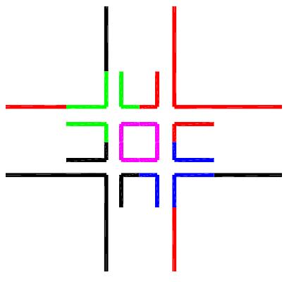
Wiring Overview The drawing that follows has a lot of information in it. Don't let it scare you. It was intended to show you a variety of things. I'll point those out one at a time for you and explain the significance. 1. Connecting only one feeder when you solder your joiners: See the upper left of the drawing. Look at the fat, black line. Note that further to the right that it says, Rail 'A.' My basic rule of track power is that every rail should be soldered to something — either the next rail or to a feeder. 2. Soldering a wire to every piece of track: Moving a little to the right, you see shorter sections of Rail 'A.' This is for when you don't solder your joiners. This is how I build my railroad — a feeder to every section of track. 3. No common rail and no common wire: Right in the middle of the diagram under Rail 'A' you see that Rail 'A' is broken. If you look down the diagram, you will see that every horizontal line is broken. All the broken lines represent wiring under your layout. This part of the drawing was intended to drive home the point that you should not have any common rails or common wires. 4. Power routing your typical turnout: The circle with squigglies is the symbol for a light bulb. Visit the first part of this track wiring section to learn about light bulbs and how they can help an operating session go smoother. This particular light bulb refers to turnouts (rail switches). See the section on turnouts to learn more about using light bulbs with turnouts. 5. No bulb needed with DCC friendly turnouts: If you have a DCC friendly turnout, using a light bulb is optional. See the section on turnouts to learn more about DCC friendly turnouts. That is it for the top section of the drawing. Now let's move down to the row with all the light bulbs. 6. A light bulb is suggested for every electrical block: A 1156 car tail light bulb can help an operating session go smoother by limiting shorts to a single electrical block. Visit the first part of this track wiring section to learn about light bulbs and how they can help an operating session go smoother. 7. Use sub buses: Notice the line labeled "GRN or CLR." Notice that it is the same length as Rail 'A.' This is to show that this wire, called a sub bus, corresponds to the portion of Rail 'A' that it serves. A sub bus is a copper wire that provides power to the track above it. Every one of my sub buses has a light bulb to separate it from the main bus — which we will get to in a moment. 8. Optional disconnects to isolate problems: The next light bulb over shows a disconnect switch. This can be used in addition to a light bulb or instead of one. If you have a problem on your layout, a switch like this can help you isolate a problem section of track. You don't have to use a switch — which costs money. Trading a little inconvenience for saving money, you can connect your sub buses to your buses with a screw terminal. That is how I do it on my railroad. 9. Use a main bus: Look at Booster #1 and the wire above it labeled "MAIN BUS of Booster #1. Look above it and you will see the main bus wire has a break in it that corresponds to a break in Rail 'A' that we noticed earlier. What is the difference between a main bus and a sub bus? Two things. One, the main bus is attached directly to the booster. The sub bus is attached to the main bus through a light bulb. If you do not use light bulbs or a disconnect switch, you do not need sub buses. The second thing about a main bus is that it services the entire "district" whereas the sub bus only services a single electrical block.
Now that wasn't so bad, was it?
Block Wiring for Large Layouts (V2.0) Contributed by Mark Gurries
Dedicated local buses allow main bus to be run out of the way of other wires typically in the back against the wall protected and away from all other wiring for minimal noise issues. Local bus follows directly under the track it feeds offering very short track feeders and easy to trace track wiring. Since it tightly follows the track, it can somewhat stay clear of other wiring. Main bus itself has very few connections making for a more reliable "protected" bus or strong electrical backbone! Downside is more wiring and more overall connections.
Simple bus requires main bus to generally follow the track. Upside are less connections and wiring to install. Downside is main bus wiring is in the middle of other wiring introducing potential noise into the other wiring and longer wire runs for the undetected track feeders. Also, the main bus must accept a undetected track feeder taps reducing its reliability and potentially reducing the effectiveness of the twisting since it results in loose twists. Caution: If you use twisted pair wiring within a detection block, it may contribute to false occupancy events. It is best to keep the wiring untwisted and keep that wiring as short as possible at the same time. This is best achieved by placing the block detector near the block it is going to detect as apposed at some central wiring panel. Running twisting cable up to the block detector is perfectly fine. Twisting after the detector is not recommended. See above diagram.
General Considerations for Running Buses Under Your Layout There are not really any rules on how you should run your buses under your layout. You can run them pretty much any way you want. For those that don’t know where to start, here are some guidelines you might want to follow. Don’t forget to review the discussions on blocks and feeder spacing covered in this webpage. 1. After conducting some tests, it is okay to join ends of a loop. I'm not recommending that you should. It's just that you can if you want to. Personally, I like having only one electrical path. If a problem occurs, I want to know about it - not mask it until two problems occur later. See drawing below. 2. However you run your buses, do not have any bus length that is more than 30’(9.5m) from your booster. See the section below on long bus runs for more on that topic. 3. Your buses do not have to be one long piece of wire. You may run buses originating at a single point, called a star, or you can branch off any place you want – a siding, for example. See drawing below. 4. If a single-track main, run your buses directly underneath the track. This should allow you to keep your feeder lengths to about 4”(10cm). See drawing below. 5. If you have a two-track main or a main and a siding, run your buses underneath the layout between the two tracks above. This should allow you to keep your feeder lengths to under 5”(13cm). You can also use this approach if you have a stub siding that parallels the main line. See drawing below. 6. If you have a yard you have a couple of choices: 6a: For every three tracks, run the bus under the middle of the three tracks. This should allow you to keep the feeders to the outside of the group of three under 6”(15cm). See drawing below. 6b: You can “zig-zag” your bus under your yard to reach all your storage tracks. Put a set of feeders at every point that the bus crosses underneath the trackwork above. This will allow you to keep your feeders under 4”(10cm). See drawing below. Note: Either 6a or 6b will work fine. I personally prefer 6a. I like my buses under the layout to have some resemblance to the track work on top of the bench. This makes it a little easier to keep your sanity while trying to troubleshoot a problem. In addition, using 6a breaks your layout into zones of three tracks. This also helps make troubleshooting easier.
Example of some of the above guidelines. Track
is in black. For simplicity, only one bus wire (red) is shown. You
will need to run two bus
wires essentially in parallel with each other.
Example of wiring under yard with 3 tracks - 6a.
Example of wiring under yard with 3 tracks - 6a. For simplicity, only one bus wire (red) is shown. You will need to run both bus wires essentially in parallel. Track is in black.
Example of wiring under yard using "zig-zag" approach- 6b. Place a set of feeders at every point that your bus crosses beneath the track. For simplicity, only one bus wire (red) is shown. You will need to run both bus wires essentially in parallel. Track is in black. You will need to "zig" to correspond with your feeder spacing. See the section on feeder spacing.
SUGGESTION: Using Blocks with DCC While you don’t need as many blocks as you would need with traditional DC-powered wiring, you will need a few on all but the most basic of layouts. Primarily, you will need blocks for polarity reversing sections. This would be for wyes, balloon tracks, and turntables, to name a few. A reversing section needs to be at least as long as your longest train – especially if your train contains a lighted caboose or passenger cars. Obviously regarding a turntable, your “train” consists of nothing more than a locomotive. For more on long trains and reversing, see the section on reversing below. You will need blocks if you are planning block detection. Primarily you will use block detection to determine occupancy on your mainline for signaling and occupancy in hidden yards. How you do that depends on what information you want to gain. If you just want to know if the mainline is occupied between two passing sidings, you only need one block between signals. If you want to have a train stop in front of a signal, you may need as many as three block detected sections between signals. Other than block detection and reversing sections, there are a few more reasons to consider blocks – short isolation and troubleshooting. If a train shorts out the track due to a derailment or picking the points on a frog, all trains operating on the booster that power that section of track will shut down. With some systems, the entire DCC system will shut down. By breaking a layout up into blocks, you will localize the problem – maybe only one or two trains will be adversely affected. Furthermore, if you have to troubleshoot a problem, you know your problem is localized to a much smaller area than what is served by the booster. How should you break a layout up into blocks? This is up to you. Creating a block for each town is always a good choice. If you have a large yard, especially one that is double-ended and worked by two operators simultaneously, you may want to break it into two to four zones. Breaking a layout into blocks for problem isolation doesn’t do you any good unless you provide some form of isolation. This can be achieved by either using an electronic circuit breaker or a light bulb. Either approach will isolate any problem to that particular block. See section regarding use of using light bulbs. If you are using circuit breakers instead of light bulbs, just substitute a circuit breaker for a light bulb. Circuit breakers cost a lot more than light bulbs, so this fact may weigh into your decision as to how many blocks you create. Especially if you opt for the more expensive circuit breaker, here is another way to further isolate your problem without significant cost. Suppose you have a town served by one circuit breaker. Instead of feeding the town by a single sub bus, break the town into two or more sub sections each fed by its own sub bus. Then connect all the sub sections to a terminal strip. Then connect the terminal strip to a bulb or circuit breaker. Now if you have a problem and your bulb lights or circuit breaker trips, you can start isolating your problem by disconnecting sub sections from the terminal strip. This beats cutting a large sub bus into pieces. You may not want a very long run of mainline on a single block. Again, this is to avoid adversely affecting too many trains. Your mainline could be part of the same block belonging to the town that it passes through. I chose to put my mainline into its own blocks and gave each block its own bulb. This immediately localizes the problem during an operating session. This approach is economical because bulbs are cheap. If you are using circuit breakers, you probably wouldn’t want to do this. How long are my blocks? They are 15-21 feet long. I did this because I am using block detection and this allows the dispatcher to know the location of a train on the layout. If you are breaking your mainline into blocks and are not using block detection like I am, you might want to consider how many turnouts you might have in a given mainline block. This is because turnouts are likely to be your source of trouble. The more turnouts you have to deal with, the longer it will take you to find your problem. There is no hard and fast rule about how many turnouts should be in a mainline block. If you are using bulbs, I suggest no more than four turnouts. If you are using circuit breakers you have to decide what works for you and your budget.
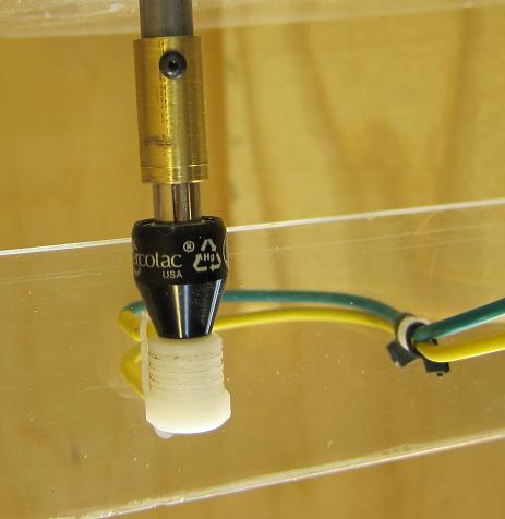
Planning a large layout? Do you have slow spots? Are you blowing decoders? Considerations for Layouts with Long Bus Wires Introduction: There are problems with long bus wire runs. The problems are difficult to describe without a background in radio or an electrical engineering degree. It would take a lot of explaining and you would have a bad headache. You don't want a headache and I don't want to give it to you. Furthermore, to really see the problems requires an oscilloscope — a tool few model railroads have. Not everyone sees the problems. Even on my previous, relatively large Digitrax layout with a few long bus runs, I didn't seem to have the problems. Note: I am told that Digitrax equipment does not seem to experience the problem like NCE equipment does. My new layout will be built using NCE equipment and I will be able to experiement with runs longer than 30 feet. The problems are out there and one of them is blowing decoders. So for that very reason, it is wise to be aware of the problems and consider doing something about them before you lose one or more decoders. A partial reason why everyone isn't seeing these problems is that I suspect that the equipment of some manufacturers is more sensitive to the problems than others. I didn't discover these problems. But since this is a website dedicated to DCC wiring, I felt that the topic needed to be included here. I am going to try to cover the topic by showing you a few pictures, giving you one simple tool you can make, and describe a few symptoms. I will avoid the deep technical discussion. One of the solutions is difficult to implement on an existing railroad. So look for instructions from owners of existing layouts. Here is what we are going to cover: I. Interference Some modelers who have long bus are experiencing interference being caused by their DCC systems. This interference may be interfering with the operation of throttles. The interference isn't too hard to understand. The relatively sharp rise and fall times of the DCC squarewave generates radio waves. Your booster is in effect, a radio transmitter. Your bus wiring is an antenna. What to do about interference: Keep your throttle and booster network wiring as far as possible from your bus wires. I don't mean they have to be on the opposite side of the room. But if you can separate them by just 6" (154mm), it will make a huge difference. If you can separate them 12" (308mm), that will be four times better. Why is twice as far, four times better? I could tell you, but I promised not to give you a headache. Just take my word for it that for every little bit further you can reasonably separate them will be very significant. Another way to cut interference is a lot harder to do. See the discussion below on twisting your bus wires. The problem — blown decoders (unterminated bus end): The second problem is due to the lack of termination at the end of a long bus run — in essence, an unterminated transmission line. As you might guess, the solution is to terminate your long bus runs. DCC wasn't intended to need terminations or cause radio interference. Still, it is hard to get around the laws of physics. Before I get into how to fix the problems, let me try to show you what is happening to your DCC signal. Take a look at these pictures. This is a picture of a DCC signal on my garden railroad. This is actually a nearly perfect DCC signal. Notice that some of the squarewaves have sharp corners. This is good. Notice that some have spikes on the corners. This is not good. Neither are the rounded corners you see on the other squarewaves. While spikes and rounded corners are not good, the world is not a perfect place. So these spikes and rounded corners are not too bad and are acceptable.
Now take a look at this picture from my HO railroad. Notice the spikes are much taller. The wavy tops to the squarewaves is called ringing. Notice also that the previously flat tops to the squarewaves are now slanted. As you might suspect, this waveform is not as good as the one above. Believe or not, my trains run on this.
If my trains run on the above, what does it take to not make a train run? It can get worse. I just don't have an example to show you. What blows the decoders are the spikes. The spikes in this picture are about 24V. Many decoders can't take over 25V. I have heard of people measuring 38V on their HO layouts! For more scope traces of a DCC layout showing high voltages, click here. How to tell if you have the unterminated bus problem: The above pictures were taken with an instrument called an oscilloscope. If you have a friend who is an electronics technician or an electrical engineer, they may work for a company that has one and will let them borrow it. Oscilloscopes can be a lot of fun. If you have a friend who can borrow one and knows how to work it, you should try to get it. Ask them to borrow a portable 'scope. If they can only get one that plugs in, tell them they will need to isolate the ground before hooking it up to your booster. You will damage your booster if you don't isolate the ground. What do you do if you don't have a 'scope? You can buy yourself a DCC voltmeter from Tony's Train Exchange or you can build a simple little circuit you can use with a digital voltmeter you may already have. Just click here for more on the circuit or Tony's meter. If building the circuit, build the peak reading circuit. If you are running HO and are reading greater than 20V, you should be concerned that you have the unterminated bus end problem. I'm going to hold off covering what to do about this problem for the moment. Let's talk about one more problem you may have first. P.S. If you can capture a 'scope trace of situations worse that what I have shown above, write me. I am looking for one or two more. The problem — slow spots (excessive inductance): The last problem related to long wiring is excessive inductance. This can make your trains run slow. Yes, small wire size or poor electrical connections are a likely culprit. Read the rest of this section on wiring and make sure your wiring and connections are adequate. If you have great wiring and are still having problems, and you have long bus wire runs, then you might have an inductance problem. How to tell if you have the excessive inductance problem: For starters, you should only be considering the excessive inductance problem if you have a long run between your booster and where your train is running slow. If you train is running slow and you only have 10-20' (3m-7m) to the problem spot, your probably have a basic wiring problem — wire too small or bad electrical connections — and not the excessive inductance problem. After you are sure you have good wiring, do the following: 1. Disconnect your booster and hook up your old DC power pack. 2. Run a locomotive that does not have a decoder in it. If it runs equally well in the problem spot as it does on a spot close to your booster connection, you may have the inductance problem. Solution for both unterminated bus end & excessive inductance: As mentioned earlier, DCC was designed with the intention that you shouldn't have to do anything special. That is true for bus runs under about 30' (10m) from the booster. So the simplest, if not the cheapest, thing to do is make sure your bus runs don't exceed 30' (10m) from your booster. If you can keep your runs down to under 30' (10m), you won't have to do anything special to your wiring! You will not suffer from untermined-bus-end-itis or excessive-inductance-itis. If you don't try to run your whole layout on one 8A booster, you will probably find that this 30' maximum is not really a problem. To prevent meltdowns, I have always recommended not using more than a 5A booster for HO. If you do chose to use something like a PM42 power management device, don't forget that you will need to count all wiring going to it as well. If 30 feet (10m) sounds really short, don't panic. There are things you can do to maximize the amount of layout each booster covers. Let's look at a few example situations. The "basic" situation: Here the booster is located in the middle of its booster district. You can run your bus wires 30' (10m) in opposite directions. Your booster can now cover almost 60' (20m) of track. Note that I said almost. The amount of wire going from your booster to your bus must be counted. If that wire is 3' (1m) long, you can only go 27' (9m) in each direction. So keep your booster close to your bus. Also, I am assuming that your bus ends about where the track it serves ends. If not, you will need to count to the end of the piece of track.
Note: I am showing a single black line that represents your bus - which consists of two wires. I have shown a single line to keep the drawing clean and simple. The "helix" or "wye" situation: You may be able to get creative and cover more track. If you have a helix, place the booster close to the base of the helix. Split off from your booster in three directions. 1. One 30' run goes to the track leading to the helix. 2. One 30' run goes to the track leaving the helix. 3. The last one goes for the helix itself. You just covered 90' of track! If you have a really big helix, you can take this idea one step further. You can make a four-way split where the fourth segment starts in the middle of the helix. Likewise, if you have a wye, you can go 30' in each direction. Of course, if you have a wye, you will need to worry about reversing which is a topic covered below.
The "yard" or "double-deck" situation: Here is what you can do if you have a yard. Also, this could be used on double deck layouts. Just suppose that some of these black lines could be on different levels. Make sure that from the end of any wire back to the booster is not longer than 30'.
Those are just some ideas of how you can get more track covered and stay within a 30' limit. In light of the above, block detectors now should be located as close to a block as possible. If you use a device such as the BDL-162 (16 block detectors on one board), you may need to use the RD2 remote sensing diodes to avoid long bus lengths. Failure to locate detector close to block as possible or putting more than the recommended number of twists per foot (1 recommended), will cause the capacitance to go up and will cause false indications of occupied blocks.
The name of this problem suggests the solution - terminate your bus ends. This is simple and inexpensive to do. Just put this "RC filter " at each end of your long buses. Yes, you will need two of these circuits for each bus — one at each end. You can make you own as described below or you can buy a ready-made RC filter from NCE. Note: Digitrax recommends that you do not use filters (aka RC networks or bus terminators or snubbers) when using their equipment as it may disrupt the track signal. I can say my first DCC layout was built using Digitrax equipment before RC filters were a good idea and I didn't have a problem that RC filterss would fix.
Values are not critical. R1 may range from 100-150 ohms.
C1 may range from 0.1-0.47uF
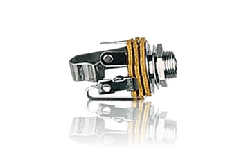
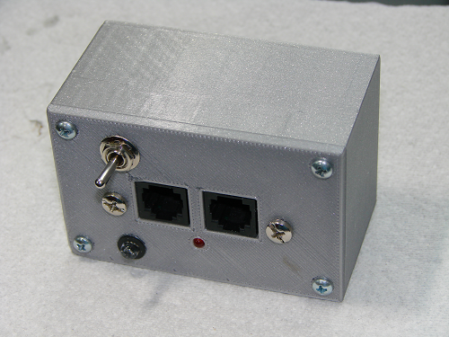
NCE Snubber (filter). Sold in a pack of two; one for each end of your bus. NCE also offers wiring kits. See their website for details at NCE.com. For more on RC Filters (Snubbers), see Mark Gurries' website at: Solution for excessive inductance: If you have long bus runs, you will need to twist your bus wires. This will also greatly reduce interference. Twisting your bus wires together is easy. Once twisted, however, it is hard to attach feeders. Worse, if your railroad is already built, twisting your bus wires together is not really an option. I suggest about 1-3 twisst per foot (or 3-9 twists per meter). Your twisted pair will contract in length as it is twisted. With 3-5 twists per foot (before you remove it from your drill) the length of cable will shrink about 3%. After you remove it from the drill, it will unwind a little bit. In case you have never used a drill to twist wire, here is how it is done. 1. Put an "eyebolt" in a variable speed drill or a cordless screw driver. Do not use a drill that you cannot run slowly. You can buy an eyebolt at your favorite home improvement store.
An eyebolt 2. Put the wires to be twisted through the eye and twist them around on themselves. Run the drill slowly and make sure the wire does not knot up while you are doing this. 3. Your wire will untwist a bit when you are done. So put a little more than the recommended twists of 1-3 per foot or 3-9 per meter. 4. Be careful when you remove the wire from the eyebolt. It is going to unwind some. Keep it under control so that you don't get hit with it and it doesn't knot up as it unwinds. What is a twisted pair of wire? Contributed by Mark Gurries There is some confusion people have in terms of what twisting the cable/bus means. There is the term "Figure-8" cable which refers to a SINGLE
bare stranded wire, made up of multiple strands of smaller wire, that are
twisted relative to each other for physical strength and integrity to act as
one solid wire that is flexible. There is nothing gained electrically. The Figure-8 term is often associated with speaker wire. HOWEVER this term has nothing to do with nor
electrically the same as true twisted cable which involves TWO insulated wires with one
wire twisting over the other wire in a spinning fashion but have no
electrical contact with each other. In DCC, one wire being the power out and the other being the power return. It is the latter that addresses the electrical issues with long cable runs.
A twisted pair of #12 AWG solid with 3.5 twists per foot. Mark recommends a minimum of 3 twists per foot. There is no doubt that electrically, this is better than 1 twist per foot as I suggest above. If you twist all the wire before you attach the feeders, you may find it challenging to untwist the wire at the points you intend to attach the feeders. Try twisting the wire as you install the feeders. That is, twist the wire up to the point you intend to attach a feeder. Then attach the feeder. Then continue twisting until you get to the next feeder. Why Twist Track Bus Wires? Contributed by Mark Gurries If you have two loosely routed bus wires that carry the booster current out to the track and back, there are electrical benefits of twisting these two wires together into what is called a twisted pair. The first benefit you get happens when you place the two loose wires that carry equal but opposite AC current side by side to each other. When we say equal but opposite, think in terms of an AC power extension cord where we have a hot and neutral wire. Power goes out and back on these two wires. This side by side pairing reduces the wire's inductance which is a property of wire that creates noise and voltage spikes when they interacting with this type of AC power and electrical layout hazards we have with DCC. However this inductance reduction can only happen when the wires are super close to each other as in NO air space or gap between them. Just pure wire insulation. This is the type of wire construction found in your everyday AC power cord. Inductance reduction is very sensitive to the spacing and the closer and tighter it is, the better the results. Romex cable has too much spacing to offer much benefit. Zip cord is better but still has extra spacing down the middle where one does the "Un Zipping". Two individual wires, preferably different colors, from spools will work best. See section on RC filters/Terminators for additional tips and techniques. Maintaining this very tight mechanical relationship over the entire run length of the pair is the key to success. If you're starting with two loose wires, such as from a spool of wire, the best way to achieve that goal is to twist them together to form a "twisted pair". The twisting action mechanically keeps the two wires close to each other all the time and forms a single cable that you can route around the layout easily. Twisting these same two wires together also provides a second electrical benefit. It will reduce the twisted pair's ability to both spread electrical noise to and pickup electrical noise from OTHER wires nearby. In a sense, twisting the two wires together forms a shielded cable so to speak. The tighter the twist (higher twist rate per foot), the better the shielding effect you get. These are the two reasons why telephone and high speed communication (Ethernet) wires are built in the form of twisted pair. Given that DCC track wiring is both communication and power all on one wire cable, layout wiring can benefit from this type cable technology. Let's be practical about this. It is understood that when you run a track bus in the form of a twisted pair, you must untwist portions of the wire to permit one to make connections. Small/short untwisted sections will not ruin the overall benefit. The goal is to keep the far majority of the wire run twisted. What to do if you have excessive inductance on an existing layout: You don't have much choice. You either twist the bus wires or limit the length of your bus feeders from the booster to 30' (10m) or less. I don't like this any better than you do — I'm an existing layout owner, too! There is a little relief. If you have a long bus run from your booster to the first feeder, you can twist only this long run. This will help. It may help enough for you not to have to do anything more drastic. Just be very careful if you twist your wires with a drill. I'm having nightmares of you going too fast, twisting and breaking your feeder wires! Thanks to Don Vollrath for his input in writing this section. Also, Mark Gurries has an extensive discussion on this topic on the NCE-Yahoo chat group. Mark does a great job of giving you the technical explanation of what is happening if you are interested. Some of the information presented here is based on his coverage of this topic on the NCE chat group.
Using High Current Boosters with Small Scales (5A and higher current boosters on HO and smaller) With the availability of 5 amp and higher current boosters, there is the temptation to use them on HO and smaller scales to save on the number of boosters you will need to buy. This can be done, but there are some things you need to know and do to avoid meltdowns and perhaps even fire.
Before we get into it, I must first say that if the booster you want to use does not have a voltage selection switch with an HO, N, or Z position do not use the booster for these small scales. The motors and lights cannot take the higher voltages put out by boosters intended for S, O, and G scales. Also, the decoders intended for the smaller scales can't take the higher voltage, either. Most of the decoders are rated for a maximum of 16 volts and booster for higher voltages put out 19V or more. The next thing you need to come to grips with is just how much power these boosters are capable of putting out. A 5A booster puts out about as much power as a 75 to 100 watt light bulb. They get hot, don't they? An 8A booster puts about 120 to 160 watts. 10A boosters can put out 200W. There is enough heat to burn you, melt things, and even create a fire. Your typical DC power pack, which was never intended to run six or more trains at once, was never made capable of putting out so much power. So realize, that while the output voltage of high current boosters is only about 15V to 20V, there is a serious amount of power here that you will need to respect. Since no HO or smaller locomotive ever needs anywhere near 5A or more current, even when you have several in a lash-up, you need to limit the amount of current available. You can do this with an electronic circuit-breaker such as the NCE EB1 or with bulbs such as the NCE CP6 or the #1156 automotive tail light bulb.. Bulbs are much less expensive than electronic circuit breakers. This means you can break up your layout into smaller districts; which makes troubleshooting easier. On the down side, bulbs don't cut the power off in the event of a short. See the section on bulbs for more on the pros and cons of their usage. I do want to say that since bulbs do not cut off the power in a short situation, do not use bulbs in parallel to get current protection higher than 2.5A.
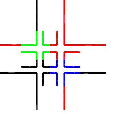
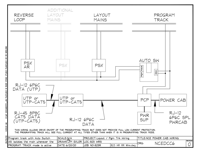
Power distribution diagram The above diagram shows a way to distribute power while limiting the current to each sub district to something less than 5A. You can use individual electronic circuit breakers such as the NCE EB1 or the multi electronic circuit breaker such as the Digitrax PM42. The key is to use electronic circuit breakers. Normal thermo-mechanical circuit breakers, such as those used in your home, operate too slowly and cannot be used for DCC. The bulb can be the #1156 automotive tail light bulb or a panel of bulbs such as the NCE CP6. Note with the bulbs it is optional not to gap the common rail shown in red. Electronic circuit breakers may or may not require you to gap the common rail. If it doubt, gap the common rail shown in red. To do so is no problem at all. The diagram shows the use of electronic circuit breakers and bulbs at the same time. You can certainly do that, but most of you will probably choose electronic circuit breakers or bulbs. I show them both just so you know you can do that. If you look in your home's circuit breaker panel, you will notice something. The circuit breakers will add up to more, perhaps much more, than your main circuit breaker. You will do the same thing on your railroad. In the above diagram, the electronic circuit breakers might be set to 2.5A. If you use #1156 automotive bulbs, they are about 2.5A. So in the above diagram, you will find that your circuit protect adds up to 10A. This does not mean you will get 10A. You will only get a maximum of 5A — the rating of your booster. Each district in this example will only get a maximum of 2.5A. Like your home circuit breaker panel, all the circuit breakers do not need to be set to the same thing. You can set some to 2.5A and others to 3.5A or whatever. Why would you want to do this? You might have a small town that will only ever have one or two locomotives in it at a time. You might set that to 1.5A. You might have an active yard with several locomotives going at once. You might set that to 3A. If this is giving you a headache, you might be wondering, can you set them all to the same thing? Sure. If you use bulbs as I do, I have in effect set everything to 2.5A. If you do this, you would break up an active yard into sub districts because there is no way I can run my yard off of a single 2.5A bulb. My yard is broken into several sub districts. As I stated earlier, your circuit protection, be it bulbs or electronic circuit breakers, can add up to more than your booster can put out. Is there a limit to how high you can go? Your total of your circuit protection can theoretically be anything. Nothing will be harmed. Rather than looking at as a total of your circuit protection, look at it from the standpoint of how many locomotives you will be running off of a particular booster at a time. If you have one 8A booster that you plan to run 10 or 12 locomotives at one time and your circuit protection adds up to 30A or 40A, that's fine. After you set up your electronic circuit breakers, it is imperative that you test them and make sure they pass the "quarter test." This is a test to ensure you have good, solid wiring as well as verifying that your circuit breakers are set properly. Use a coin, pliers, or screwdriver, short your track and make sure your circuit breaker shuts down. If your circuit breaker does not shut down and neither does your high current booster, a meltdown is likely (see photo above) and a fire is possible. When using bulbs, when you short your track, the bulb should burn brightly to indicate that you have good wiring. A bulb that is half lit indicates a bad connection. Your trains will run poorly and wherever your bad connection is will get hot, perhaps dangerously so. How do you set your electronic circuit breaker? This can be easier said than done. For this reason, I prefer electronic circuit breakers that you can set with jumpers, such as the NCE EB1, or through software settings, like the Digitrax PM-42, where you just follow the directions to set the trip point.
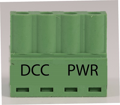
Modular Wiring and PowerPole Connectors by Doug Stuard
Cutting Power to Yard or Roundhouse Tracks Before discussing how to cut power to tracks, let me first address whether you should do it at all. You don't have to do it unless you want to. Small layout owners with only one operator may not want to bother. There are three reasons you might want to cut power to tracks. One, because you have a lot of lighted cars or locomotives with sound drawing a lot of power. Two, because you don't want trains to take off unexpectedly. Three, silence locomotives not in use. If your concern is too much power draw, make sure you have a problem. Is your booster or electronic circuit breaker tripping out in your yard or roundhouse? Then you might have a problem. Be sure it is not due to wheels going across your turnouts. If you have multiple operators, there is a danger of someone unknowingly selecting a locomotive somewhere on a layout and unknowingly sending it flying off a track. Cutting power to a track is one way to silence an unused locomotive. Most sound locomotives have some way to do that without cutting power to the track. But if you are using basic throttles without the capability to access the sound decoder's silencing function or have different sound decoders that, of course, each use a different function key to silence them, cutting the track power might be the way to go. If you have decided you want to cut power to a yard or roundhouse complex, you have a few different ways to do it. One thing they all have in common is that you only need to cut the power to one of the two rails. Approach #1: Install a SPST toggle switch feeding each individual track that you want to cut power to. So if you have a seven track roundhouse, you would use seven SPST switches. Make sure they are rated for at least an amp; an amp and half is better. Just turn on the track of the locomotive you want to run. Approach #2: Install a SPST rotary switch with its output going to each individual track to be controlled. Typically these are available in 6 or 12 positions, but are available in more if you are willing to pay the price. Radio Shack carried a 12 position rotary switch, but it was only rated for 300mA. It might work for a while, but eventually may fail due to pitting of the contacts when used at higher currents. Higher current commercial rotary switches are not cheap. If you use all positions of a rotary switch, then one track will always be powered. This may or may not be an issue for you. If you don't use all positions, then you have the option of having an all-off position(s). Approach #3: Use SPST toggle switches to turn off the power to multiple tracks. If you have an eight track roundhouse or yard, you could use two SPST switches; each controlling four tracks. This is similar to approach #1, but with less wiring and cost. If you don't have the problem of too much current draw with all tracks on, you could simply use one toggle switch to control all the tracks at the same time. There is no one right approach. Pick the one that appeals to you most.
Wiring Reversing Sections - An Introduction Reversing isn't that hard. There are just a few basic rules which I have outlined below. What makes it hard, if anything, is that you can be very creative how you implement them and the possibilities are endless. All the possibilites can drive you crazy if you aren't careful. There is a lot of material here. Read over this introductory material and then look at all the diagrams and see if you spot one that fits your situation. Be sure to follow the diagrams in this webpage or the instructions for your reverse section controller carefully. For a brief introduction to reversing, see the discussion of this topic in the section DCC for Beginners. Topics include: what happens to a train when it enters a reversing section, if a train doesn't care about polarity, why reversing sections are necessary, and what happens when two trains enter a reversing section. I have provided many diagrams below. If you don't think any of them fit your situation, you can upload a drawing of your layout and ask a question on the Q&A Forum. I have provided some diagrams with all the wires and some only showing a single rail or wire using black for non-reversing blocks and green for reversing. My goal was to give you all the detail you need without making all the drawings to complicated to follow. There are a few basic things you must do when you wire a reversing section: 1. Make sure the reversing section is at least as long as your longest train. If you are not using any lighted cars, the reversing section only needs to be longer than the locomotive or lash-up of multiple locomotives. What happens when two trains enter a reversing section at the same time or a train is longer than the reversing section? See the discussion of this topic in the section DCC for Beginners. Making sure that your reversing section is long enough seems to be the thing that gives people the most trouble. How long is long enough may only be 18" for a locomotive to 12' for a lighted passenger train. Just make sure you plan this right because it may be very hard or impossible to change once your railroad is built.
Images used with permission of Kalmbach Publishing If you have a consist/lash-up of locomotives, then your train is the length shown in red.
If you have a pusher, then your train is the length shown in red.
If you have lighted passenger cars, then your train is the length shown in red.
If you have a lighted caboose, a caboose with block detection, or a F.R.E.D. powered by the track, then your train is the length shown in red.
If you have Soundtraxx's Car, then your train is the length shown in red. If you don't have any Sound Cars, what are you waiting for? Cars with speed sensitive clickity-clack and wheel squeal is very cool!
If all your cars have resistors across the axles for block detection, then your train length is that shown in red. Normal freight cars that don't draw power don't count in your determination of what is your longest train if you do one thing. However, if you are using freight cars with sound in them, these will count in determining what is your longest train. Make sure you think about whether you will ever use these. As I just said, changing a reversing section after the railroad is built is hard. It is possible, that even cars that don't draw any power and have metal wheels, might trip a reversing section. A train would have to be crossing one end of a reversing section when a metal wheel crosses the other end. If this happens to you, make the gaps in your track a little wider so that a metal wheel can't bridge both sides of the gap. Fill the gap with epoxy. 2. Double gap the track at both ends of the reversing section. 3. Do not connect your main bus to your reversing section in any way. Your reversing section must only be connected to your reverse section controller, reversing relay, or reversing switch. 4. Do not put two reversing sections adjacent to each other unless one of them is reversed using a throat controlled relay. This is because this type of reversing is not performed automatically by detecting a short. This arrangement will not cause the two reversing sections to buck each other. Reversing Crossovers Reversing crossovers seem to be the biggest problem and most common of all the different types of reversing track plans. I think this is because of all the different types of reversing track plans, it occupies the least amount of real estate and may be the least expensive to implement. I also think crossovers cause the biggest problem because people who are not knowledgeable about reversing implement them without knowing they are about to run into trouble. So let's take a few minutes to understand crossovers.
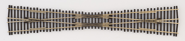
Siding Crossover - Both of the above crossovers are electrically the same. Track polarity does not change as a train traverses the crossings. The siding crossover might be used when a modeler makes a long siding and wants to be able to hold two trains. Since the above crossings are electrically the same, study the top example as it is a little easier to visualize. Before studying the crossing, note the loop at left. Note that the red rail goes from being on the top and around to the bottom. Now look at the crossing. No matter which side of the crossing a train is on, the red rail is on top. So if you are building a crossing into a siding, no special wiring considerations are required.
Reversing Crossover - Both of the above crossovers are electrically the same. The track polarity DOES change across the crossover. Modelers commonly build this type of crossover into their track plan because they want a way to reverse their train. Hint: If you are reversing the direction of travel, you will also be reversing your track polarity and have built a reversing section. Again, since both of the crossovers above are electrically the same, study the two single crossovers as they are a little bit easier to follow. Look at the left crossover. The orange diagonal rail going through the crossover connects to the blue rail on the bottom and the red rail on the top. Similiarly, the purple diagonal rail connects to the red rail on the bottom and the blue rail on the top. Note that whether you build one crossover or two, you still have reversing sections. If you are building this type of crossover into your layout. continue along in this website to see what you need to do to successfully wire your layout and avoid shorts. Note that since crossovers don't take up a lot of space, you will probably have train length issues. So if you skipped over the images discussing train length above, go back now and study them before continuing. Now I will discuss examples of all the types of reversing sections. If building a reversing crossover, you can skip to those examples.
Here is a typical layout with two reversing sections. The first thing a modeler wonders, is can I combine the two reversing sections in a way to use one reverser and save money? The answer is yes. I will show you how below. But there is one BIG caution that applies to all large, multi-entry reversing sections; especially when you have multiple operators. You must avoid mutiple trains crossing into/out of the reversing sections at the same time or things will short out and stop running.
You can be creative with your reverse sections. Here you have two balloon tracks, but by making the mainline the reversing section, you will only need one automatic reversing module.
Wyes are a common way to reverse trains. Indoors, they can take up a lot of space. They are a little more palitable if each leg goes somewhere. Still, each side of the wye tends to be short indoors and may not hold a train. (My outdoor wye was so large that each side held at least one train. If you are planning using lighted passenger cars, using a wye with one of the sides as the reversing section may not work for you. See the wyes below where I use one of the legs as the reversing section rather than one of the sides If you use a leg of a wye as reversing section you might be able to use a relay rather than an automatic reversing module. A relay is about half the cost of a reversing module. Be sure to read about throat controlled relay reversing sections below. Alas, the half-price relay won't be an option you can use if your reversing section will have multiple entry points. That is discussed below, too.
Keep your options open! Here again, I switched what portion of the railroad is the reversing section!
There are lots of options here. Note that the word option here also means pitful! A turntable could be placed at the end of a wye as shown, where, if the only thing you were going to reverse was a locomotive, then the leg going to the turntable could be short. But if you ever think you might turn lashed-up locomotives or a lighted passenger train, the leg of the wye would still need to be long.
I hope you don't like this because this is something you cannot do normally. The wye is an automatic reversing section and so is the turntable. You cannot have two automatic reversing sections adjacent to each other. You can do this if you use a PSX-AR by www.DCCSpecialties.com It has a feature for adjoinging two reversing sections when using two of their products.
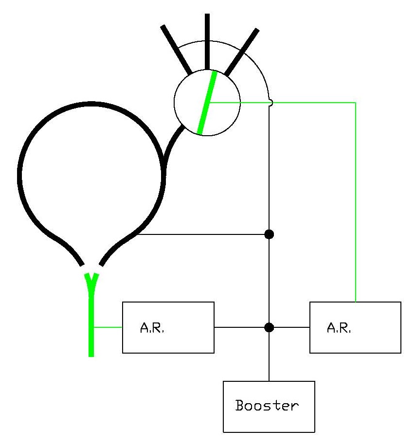
In this example, a relay is used to reverse the loop. If you are using an electronic reverse section controller, just substitute it for the relay in the above diagram. Note that the blue and magenta main bus is not connected to the red and green loop. If you want to auto-throw a turnout that is set against a train, such as with a balloon track, there are a couple of ways to do it. The easiest and perhaps the least expensive is to use the DCC Specialties product called The Hare using a feature they call "Auto Throw." They also have a product called the PSX-AR. www.DCCSpecialties.com Both can change a turnout possition before the train hits a turnout thrown against it. The documentation describes how to do it, so I won't reproduce it here.
If you have an oval with a crossover, wire as shown above.
The ARSC is the auto reverse section controller This concludes the introduction. Now read on for more information and details.
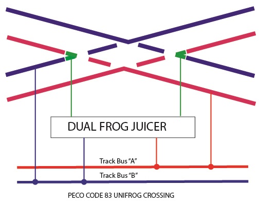
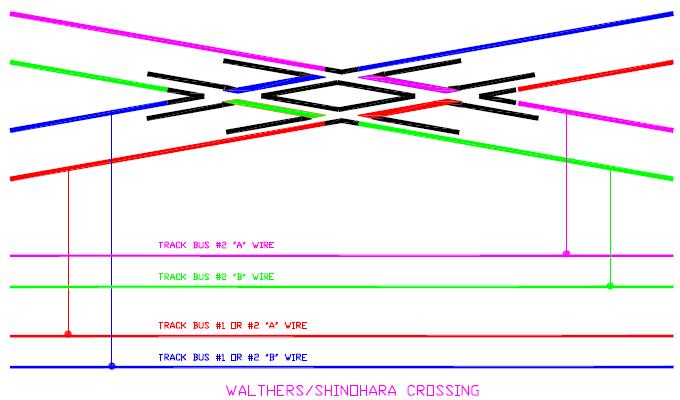
Setting Electronic Circuit Breakers For the average model railroader, you may be able to use an Electronic Circuit Breaker (ECB) right out of the package If you are using a Tam Valley Depot Frog Juicer for powering your turnout frogs, you might have to tweak your ECB. I say might because I am using Frog Juicers and the ECBs I use, work just fine. If you are having trouble with Frog Juicers and your choice of ECB, then read the rest of this section. If you do have to make changes to your ECB, you may need to add a delay to it. More on that in a moment. Your booster will shut down if a load, usually a short circuit, draws more current (amps) than the booster is designed to handle. The booster shutting down protects your booster not your locomotive. Protecting your locomotive is the job of the ECB. Boosters are often designed to supply 5 or even 8 amps. This can cause a meltdown of your locomotive and track. A modern, typical HO locomotive draws about a 0.5 amps; maybe a little more. N is obviously much less. Even O or G scale trains don't draw much more than 1 to 1.5 amps. And that is all with sound. Lashups, often done more in the smaller scales than the larger ones, don't draw more than a couple of amps. The bottom line is that ECBs do not, and should not, be set at just a little below your boosters trip limit. Set them lower; like 2 or 3 amps tops. Fortunately, most ECBs default to this suggested lower limit. So if you are happy with this, you don't need to do anything to your ECB. Use it as is. Another reason for using ECBs is to break up your booster district into smaller districts - like maybe a town. This does a couple of things besides just protecting your locomotive. One, you won't be having 10 locomotives in a smaller district. If you have a large district and would have 10 locomotives, you would need your ECB set high. This is a bad idea. Make your district smaller. Two, when your ECB trips, the problem will be a limited to a small area; usually something sensible like a town. And three, you will not be shutting down a large portion of your operating session and irritating your friends. If you think you need to change the trip point or time delay in your ECB, consider this worst case example: BOOSTER ---> ECB ---> Frog Juicer If you are not familiar with Frog Juicers, they are like a mini reversing unit that corrects the polarity of a turnout frog. Frog Juciers are particularly useful for people who want to use ground throws and still power route their frogs. They work by detecting a shorted frog and reversing the polarity of the frog. For things to work right, the Frog Juicer needs to act before the ECB does. If you have a real short, the ECB needs to trip before your booster does. So there are two things you need to have right for everything to work smoothly. One, you need the current trip of the ECB to be higher than that of the Frog Juicer if you are using them. Whether you use a Frog Juicer or not, the current trip limit of the booster needs to be higher than your ECBs. You want the Frog Juicer to do its magic before your ECB shuts down your train. When you have a short in your town, you want the ECB to shut down before your booster does. This is usually easy to get right. The Frog Juicer trips around 1.5 amps, most ECBs trip between 2 and 3 amps, and most boosters trip at 5 amps. So often, you won't have to do anything. Note: Frog Juicers do not have any adjustments. They only have 3 wires. Just put them in five minutes and they work. They are great. There is another thing you need to get right - trip timing. If the timing of your ECB is faster than the reaction time of the Frog Juicer, the ECB will shut down before the Frog Juicer gets an opportunity to do its thing. Likewise, if the timing of your booster is faster than your ECBs, the booster will shut down before the ECB gets to act. Again, things right out of the box usually work just fine. In older boosters, you needed to set the trip timing for the booster longer if using ECBs. If using Frog Juicers, they are your line in the sand since they are not adjustable. If your ECB trip current is set to 2 to 3 amps, but is still tripping before the Frog Juicer reacts, then slow down the trip timing of your ECBs. Your ECB trip timing does not need to be right on the edge of the trip timing for the Frog Juicer. It can be a little more than that. Set it at something that works reliably without driving your nuts. I've never had to adjust mine, so I'm guessing you might find that you need to delay your ECB by 8 or 16 milliseconds more if it is tripping too fast. Same goes for your booster (or command station/booster combo). You need to set the timing of these to be long enough that your ECB gets a chance to act. I think my early command station/booster only had the option of setting the timing to be 1/8 or 1/2 of a second. I had to set it to 1/2 of a second.
Auto-Reverse Controllers and Electronic Circuit Breakers Auto reverse controllers work by detecting a short. Assuming the short is caused by an incorrect polarity, it changes polarity. Electronic circuit breakers work in a similar fashion. They detect a short, but instead of reversing the polarity, they cut the power to the shorted section. Neither auto-reverse controllers or electronic circuit breakers act instantly. If they did, there might be false reaction by these devices. So they have brief delays and then act. If you put an auto-reverser and an electronic circuit breaker in series with each other, the devices will compete with each other and you will probably get unexpected and undesirable results. Therefore, you should not put an auto-reverser and an electronic circuit breaker in series with each other. If you feel you have a section of track that needs reversing, then that may mean no electronic circuit breaking. There are a few other options. Perhaps you have a balloon track that you can use a relay connected to the throat turnout to control reversing the polarity. Since this is not an automatic reverser, you can use an electronic circuit breaker with this. Using a relay like this is described on this web page below. If you need auto reversing and want an electronic circuit
breaker, then use a PSXX-AR by www.DCCSpecialties.com
a BXPA1 by Digitrax, or an AR10 by NCE. They are single devices that contains both of these functions that work together.
Don't look at a PSXX-AR as a pricy auto-reverser. Look at as a auto-reverser
and electronic circuit breaker; which if priced together, is the price
of a PSXX-AR. So it is a good value. The PSXX-AR works well and you don't
need to fidget with trip levels as you do with lesser-priced auto-reversers.
SUGGESTION: Have a Simple Reverse Loop or Wye? You Might Not Need to Buy Another Booster! Relays are about half the price of auto reversing controllers. You will need a 12V power supply, like a wallwart. I have a 12V bus that runs my sound effects and lighting of buildings. So I didn't have to by a 12V supply just to driving reversing relays. Note: Some auto reversing modules have a relay in them. I still refer to these as auto reversing modules and not throat controlled relays. If you have a simple reverse loop or wye, you can simply use a relay with an existing booster. The relay is controlled by a set of contacts on the throat turnout. A simple reverse loop is one that connects to your main trackage through only 1 track. If you don't have a simple reverse loop or wye, but you do have a track arrangement where a reverse polarity will take place, you may have to buy another booster or an automatic reverse section controller which is made by most of the DCC manufacturers. If you have a loop or a wye where trains can enter it from more than one track, you may not be able to take advantage of this idea. If the train is moving when the throat turnout is flipped, it might jerk a bit. You probably won't be throwing the throat turnout while the train is moving if you are going through a wye. But you might be moving when going through the reverse loop. Think about it; you may not use your railroad that way. I intend to use reverse loops for off layout connections. My train leaves the layout and onto the reverse loop. There it stops. Sometime later it returns. So the problem of a jerky movement never takes place or would be seen if it did. How will you know if it will jerk? Or worse, for a sound equiped locomotive, an interruption on the sound. When I use relays to reverse trains, I haven't noticed a jerk. But you may have a problem when using a Tortoise or other slow motion switch machine contacts to reverse your train. This is because the interruption of power maybe longer than with a quick-flipping relay. Don't panic, if you are using Tortoises as I am, use the Tortoise to activate a traditional relay which flips quickly. I show you how to do this below. Just look for the balloon tracks below with the Tortoise and relay.
Balloon track using a turnout that has power routed frog rails.
Balloon track using a turnout that does not have power routed frog rails.
SW#1 is attached to your turnout or switch machine. You may have to experiment with swapping the wires on SW#1 to make sure the locomotive runs fine through the turnout without shorting your booster. The wire on SW#1 that also goes to the relay may have to be moved to the other contact on SW#1 to get the train to run properly through the reverse loop without shorting your booster. The reason I can't say for certain which way to wire these up is because it depends on how they are oriented with respect to your turnout. However, if you build your turnouts and their switch machines all the same way, once you figure out how it goes, it will be the same for all your turnouts. If you are looking at this drawing to learn how to hook up a turnout, you don't need the relay! The relay is shown for those considering using a relay to avoid buying a booster. You only need SW#1 attached to your turnout.
A simple wye is one where the tail does not reconnect with the rest of the layout. It is okay if the tail track feeds a stub-end yard. As long as none of the stub tracks reattach to the rest of the layout, you have a simple wye that can use a relay to handle the reversing. See the two examples below.
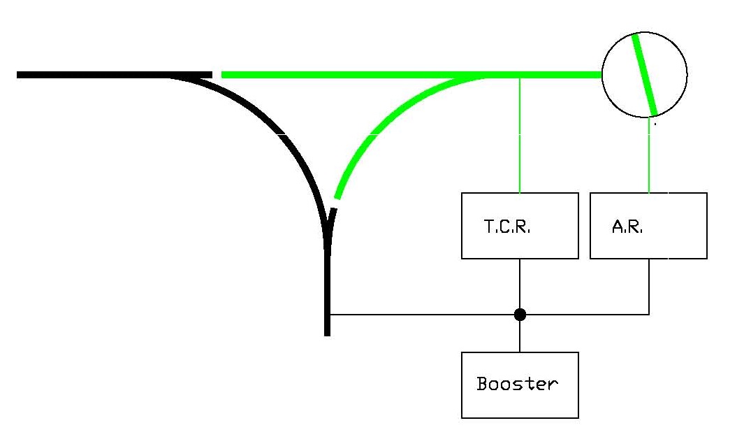
I use the configuration as in "F" on my garden railway and on my HO layout. In both cases, I used a relay to control the reversing of the green/blue tail track(s).
Reversing a Balloon Track with a Tortoise This is the lowest cost way to reverse the polarity of a balloon track. If you have a wye with a tail track, you can use this approach on a wye as well. Just follow these easy steps. 1. Determine which diagram below applies you. Under each diagram, I have listed some popular turnout types. Find yours.
Peco Electrofrog, Pilz/Elite/Tillig, Orr (after modification)
Atlas, Kato, Micro Engineering, BK Enterprise, Roco, Walthers DCC Compatable turnout The diode shown in black should be a 1N4001 or better diode. The relay can be any 12V, DPDT relay. See section on Parts for relays. 2. Install your Tortoise and get it working. I have shown a red/green LED pair. You can either use a single LED that has them both built-in known as a dual-color LED. Or you may use two separate LEDs if you want. You can even use two of the same color. Before soldering wires to your LEDs, first hook them up with alligator clips. If the indication is backwards from what you want, swap the wires going to the LEDs. Then solder your connections to the LEDs. Note: No dropping resistor is needed. That function is performed by the Tortoise. 3. If you are using turnouts with powered frogs (such as the Atlas, Kato, etc. above), connect your frog wire temporarily as shown to the green wire on the output of the relay. Run a locomotive with all wheel pick-up, like a diesel across the frog. If it shorts, move the frog wire to the red output of the relay. (If you are using the turnout that doesn't have the isolated frog, you need not perform this step. Go to step 4.) 4. Hook the red and green wires to the track. If a locomotive shorts when it goes across the track into the balloon, swap the red and green wires going to the track. You're all done!
Balloon track with power routed frog using a DCC turnout or stationary address decoder to control a Tortoise. One of the sets of contacts on the Tortoise are used. Note that the relay has a third set of contacts that will replace those on the Tortoise you had to use. Note that most relays, especially those with 3 sets of contacts, cannot be driven by a DCC Turnout Controller. You may be wondering why this diagram is in black and white. I am, too. The software I am using is 9 years old and the original drawing that I made of the color versions above were drawn in 1996. I made my new drawing, based on the old ones, in color. But when I print the new drawing, it comes out black and white. Go figure!
If you have a reversing section and you will only be running one loco and a couple of passenger cars, you can use the Tortoise's internal DPDT switch to reverse the polarity. I don't recommend this if you will be running two or more locomotives in HO. A couple of locos in N or Z should be okay.
Here a balloon track but with the reverse section limited to the part that isn't on the mainline. Still, you cannot use a throat controlled relay because the balloon track still has two entry points. You will still need to use an automatic reversing module.
Other Wye Configurations: Here are some sample wye configurations. There is nothing magic about them. I am providing these to give you some ideas. A reason to use a particular one is to minimize the need to trigger the reversing circuit. Some systems hesitate briefly while the switching takes place.
I have shown these wyes drawn with a straight side. I only did that because it was easy to draw. Please realize the orientation of the wye can be any way you need it to be. In fact, look at "B" and "D" carefully. Turn "D" on its side. "D" and "B" are essentially the same! "D" and "E" can be used with tha throat controlled relay to do the reversing if the reversing tails don't loop back around to join the main track in any way. In my garden railway, I attached a five track yard to the reversed tail of the above diagrams and did not go anywhere else. In this is situation, it works fine. Remember the basic rule of reversing sections: the reversing section must be at least as long as your longest powered train. Configuration "C" appears that it may be hard to implement if you have a lighted passenger train. It could also be a problem if you have a lighted caboose. If the only powered unit is your locomotives, than the reversing section in "C" may be able to be short. If you are lashing up locomotives, be sure it is at least as long as your longest lashup.
Reversing Through Wyes for Lighted Passenger Trains and Long Lash-Ups
The configurations shown below will handle the reversing needs of a wye where long, lighted passenger trains or long lash-ups are involved. I show a spur and a siding to illustrate that you may have a reversing section that contains these trackwork features without a problem. I have also shown black/red tracks leaving the far end of the reversing section. If you just read the section above about simple reversing sections, these two examples do not qualify as simple. Therefore, you will need an automatic reverse section controller — which is available from most DCC manufacturers. The final thing to notice is the somewhat subtle difference between the two diagrams below. The diagram on the left only involves the turnout in the reversing section. This is how the wye in my garden railway is wired. The diagram on the right shows that most of the two legs of the wye are also involved in the reversing section. The differences between these two diagrams is not profound. I just wanted to illustrate to you that either way works. The diagram on the right simply allows you lengthen your reversing section or "pull in" the far end of the reversing section as is shown.
Using Double Crossovers with Balloon Tracks The dogbone with the crossover appears to be very popular. Here are several approaches to the reversing issues such a track plan presents. I'll present thoughts on each one of them. The track shown in black is connected to your non-reversing booster. The track shown in green is connected to your reversing booster.
Reverse sections at each end. The green sections are connected to auto reversing section controllers (ARSC). I also call this automatic reversing modules. Use whichever name suits you. . If you connect each green section to its own ARSC shown above, you will have the generally most useful version of the dogbone and crossover. This is because each reverse section has only two entry/exit points. The fewer entry/exit points for each reverse section, the less likely multiple locomotives will be crossing multiple entry/exit points at the same time. This will likely happen on a large layout with multiple operators. Also, the main, non-reversing section shown in black can be very long and if necessary, can be powered by multiple boosters. As always, the reversing sections must be longer than your longest train — whether it be 5 diesels in a lash-up or a lighted passenger train. If the layout is not large and you are the only operator running one train at a time, then you can power both reversing sections by the same ARSC. If you want to save some money up front, you can power both reversing sections with one ARSC. If problems develop from multiple locomotives crossing the entry/exit points, you can always add the second ARSC.
Reverse section in middle. Only use this plan if you definitely will only run one train at a time. This plan has four entry/exit points and makes the main portion of the layout the reversing section shown in green. This plan won't work if the mid section is very large and needs to be powered by multiple boosters. If you have multiple locomotives running at once and you have trouble with several of them crossing the entry/exit points, this plan will involve the most work in rewiring the layout to be like the plan shown above with two ARSCs.
Reverse section down one side of crossover. Measure from the center of the "X" to the end of the green zone in each direction. The green zone from the top to the "X" must be at least as long as your longest powered train as described in the paragraph above. Also, the green zone from the "X" to the bottom must be at least as long as your longest powered train. The reason for this is that by having the crossover in the middle, you have effectively created three entry/exit points into your reversing zone. At all times, when a train is entering and exiting a reversing zone, that reversing zone needs to be at least as long as the powered portion of that train.
Single-ended dogbone. The green area must be at least as long as your longest powered train. Maybe that is 5 lashed up diesels. If you have a lighted passenger train, then the green section must be as long as all the lighted cars. If you fail to heed this rule, you will short out your booster.
Using a Common Passing Siding in a Dogbone If you want to use a dogbone with a common passing siding, just make the entire passing siding a reversing section. You will need to use a reversing section controller. Make sure your reversing section controller is set to trip at a lower current setting than your booster can put out.
Reversing Loops That Are Close to Each Other:
Here is a point-to-point layout with two balloon tracks in close proximity to each other; maybe even one on top of the other. For small layouts with maybe only one operator, this would work. Running too many trains and with too many operators, you may have two trains cross into two reversing sections at the same time and short things out.
Here are the same stacked balloon tracks, but using seperate reversing controllers - either auto reversing modules or two throat controlled relays. Yes, you could even use one of each!
An Example of a Large Layout With Complex Trackage:
Above is a simplified diagram of my layout. Note that your balloon tracks don't have to be simple balloons. One ballon has several sub tracks. The other has several double ended yard tracks. One turntable has engine house tracks and the turntable is part of a yard. The other turntable is part of a yard and industry, but here the turntable is only used for reversing. My main line is long and two of my yards are big, so I have six boosters.
Adjacent Reversing Sections Below I show how to have two adjacent reversing sections. Normally, you cannot have two adjacent reversing sections because they will buck each other when a train goes from one reversing section to another. Throat controlled relays do not change polarity automatically based on a detected short. So a reversing section using a throat controlled relay can be placed next to an automatically reversing section that switches polarity based on a detected short. If you need to have two automatic reversing sections close to one another, you will need a fixed-polarity section between them. This should be at least the length of a powered truck and the length of your longest locomotive recommended so that you don't have to worry about which wheels are power pick-up wheels.
Normally, you cannot have two adjacent reversing sections. Here is an example way to beat the problem if you really need two adjacent reversing sections. You make the balloon track a standard, non-reversing section and you instead make the mainline a reversing section. You can be creative with reversing!
Here is another way to have two adjacent reversing sections. The balloon track uses a throat controlled relay to reverse the balloon track.
Here is another example of adjacent reversing sections that will work when using a throat controlled relay.
Reverse Section Indicator Do you want an indicator that indicates when a reverse section is at the opposite polarity of your main track? Go to the section on Signaling for a circuit.
SUGGESTION: Automatic Balloon Track Control Use a DCC autoreverser to control the turnout leading to a balloon track. See the circuit in the section on turnout control.
PSXX-AR & PSXX - Use Both in Series? There is the common belief that the PSXX-AR contains both the PSXX and an AR. Yet DCC Specialties' documentation clearly shows a PSXX-AR in series with a PSXX. So I wrote Larry Maier, the engineer behind these products and asked him why should a PSXX-AR be put in series with a PSXX. It turns out the PSXX-AR does not contain an electronic circuit breaker and you should use both of these products in series. Below is the answer Larry sent me. There are two reasons for the recommended configuration. 1) The PSXX circuit breaker not only turns the output off in the event of a short circuit, it also limits the fault current to the same value as the trip current setting. To my knowledge, all other circuit breakers allow the full fault current of the booster to flow during the time between the onset of the fault and the termination of power to the track. This fault current can easily be 30 amperes or more depending on the booster (the highest I have measured is 67 amperes). The fault current can cause damage in two ways. First is by simply heating the fault (resistive heating). The second is by storing energy in the magnetic field of any inductance in the wiring. This energy is released as a voltage spike (or spikes) during the fault. The voltage spikes can damage decoders depending on the energy they contain. In both cases the heating energy and voltage spike energy are proportional to the square of the current. Hence, if the PSXX only allows 5 amperes into a fault instead of the full booster 30 (or more), there is a reduction in the amount of energy that can damage equipment by a factor of 36. The PSXX-AR does not have the current limiting circuitry that the PSXX breaker has. However, if the PSXX-AR is fed from a PSXX breaker, then the PSXX-AR provides the same current-limiting benefits to the reverse loop as the PSXX breaker without the added cost of the current limiting circuitry on the PSXX-AR. The PSXX-AR can be used without a feed from a PSXX breaker, but the reverse loop will not then have the benefit of a current limit. 2) A problem with reverse loops is that the fault current from the mis-matched polarity can travel through a significant length of wire depending on how the reverse loop is wired. This length of wire can have series inductance, which can distort the current waveform making it more difficult to detect the mis-match. This can delay or prevent proper reversal of the polarity. For this reason, we recommend that the input power to the reverse loop controller be connected to the "normal" track just adjacent to the reverse loop. This results in the shortest possible path for the out of phase current to flow giving the best possible reversing response. If the "normal" track is fed from a PSXX breaker (which we would expect), then the PSXX-AR is in series with the PSXX breaker, giving it the benefit of fault current limiting while providing the best reverse response. The PSXX and PSXX-AR are designed to work together in this configuration with both set to the same current value.
Wiring Turntables and Transfer Tables If you are using the Walther's turntable with the blue controller and you want to automatically cut power to stall tracks to silence locomotives, go here: ACM relay control. Also, if you are using the Walther's turntable, you will find this next photo useful:
The connector on the bottom of the turntable itself isn't labeled. This will help you get it right. Below are examples of how to wire turntables, transfer tables, and combination turntable and transfer tables (apparently used in Europe) when using DCC. Note that in all cases, you will always have two sets of things to wire. DCC always goes to the bridge in the turntable or transfer table and all the stall tracks. You also have to wire the rotation/translation motors. These can be DCC controlled if you wish. No matter who you bought your turntable/transfer table from, they had to provide for a way for you to apply track power separately from however they provided for you to control the turntable/translation motors. Stall Tracks Some people like to kill the power to the stall tracks to avoid locomotives accidentally taking off. This can happen if someone has accidentally acquired a locomtove in your roundhose. To kill stall power, you can do this two ways. One, is to put individual SPST switches cutting power to one leg of each stall track. This is your best insurance against accidental launches into the pit, but it is a lot of work. Two, you can use a single SPST switch to cut the power to all the stall tracks simultaneously. This is a lot less work if you are worried about accidental launches into the pit. If a locomotive starts to move when you flip the switch, you can quickly flip it off. Since there are so many ways to approach killing your stall tracks and wanting to make sure you understood the basics of wiring your turntable/transfer table, I have not shown any kill switchdes. If I need to add another diagram, I will.
Note that the turntable uses a reversing controller. (You can sometimes use a split ring as described below.) This is because a turntable can turn a locomotive around and therefore, the track polarity needs to be reversed. A transfer table can't turn a locomotive around and does not need a reversing controller.
Transfer tables use a little less room that a turntable and roundhouse, but normal transfer tables can't turn a locomotive around. A combination turntable and transfer table can do that. I don't know much about these, but I can wire 'em!
DCC Control of the Rotation/Translation Motors Some turntables/transfer tables come with indexing and a controller. If yours is one of them, I'd be inclined to use the system they provided. Indexing can be a lot easier to use than eyeballing the alignment of tracks. No doubt, you will find manufacturers providing ways to control your turntable/transfer table with DCC as well provide indexing. If you don't have indexing or don't want to use it (indexing may not be very prototypical), you might want to consider using DCC to control your rotation and translation motors. There is the immediate appeal of not having a control panel item and the ability to control your turntable using your throttle is alluring. Before you make this decision, there is something you should think about. Turntables and transfer tables are almost always in yards. There you will frequently be acquiring locomotives to your throttle. You also may have two locomotives assigned to your throttle - the yard locomotive and the one that is about to go out on the road. If you have this situation and you still want to control your turntable/transfer table with DCC, you may want to buy a basic DCC throttle from your system's manufacturer and dedicate it to this purpose. This partially kills the idea of not having a control panel, but you still might find it easier to mount a small jack in your facia rather than a larger controller.
Powering the Turntable Track Some turntables come with a built-in method of getting track power to the turntable bridge. Some turntables, notably kits, do not necessarily provide a good way to get power to the bridge. The Split Ring Below are two drawings of turntables. Perhaps being full circle they are a bit unrealistic, but they serve a purpose of being somewhat universal as there are a large number of configurations that can be used with a turntable. Besides, admit it, you would really love a full circle turntable, wouldn't you? Turntables require some form of reversing. The first drawing depicts a turntable that uses a split ring to affect the reversing function. The split ring could a split ring rail around the pit. Or it could be split rings located under the turntable. Note the yellow zones shown on the split ring. This is the disadvantage of the split ring approach. You need a dead zone represented by the yellow sections. No working stall tracks can be placed across from the yellow zones. The width of your dead zone is determined by the width of your split ring pick-up. Your dead zone may be one to perhaps three tracks wide. If you are planning a roundhouse that is a semi circle or larger, you can not use the split ring approach.
If you desire to have two tracks directly aligned from each other where a locomotive can pass across the turntable without turning it, you must wire the stall tracks as shown above. That is, all the blue tracks are wired together and all the red tracks are wired together. Notice that the wiring is reversed on the bottom half of the above drawing. I have highlighted two blue and two red rails so that it would be obvious to you where the wiring needs to be reversed. If you mentally rotate the turntable bridge, you will see that a locomotive can pass across it while maintaining proper track polarity. I show the split rail as being red and blue as well. However, I need to make clear that what I show as blue and red on the split ring may need to be reversed on your layout. It depends on which rail of the turntable bridge is wired to which split ring pick-up. If a locomotive tries to move from a stall track and shorts out as it makes its way onto or off of the bridge, you need to reverse the two wires supplying track power to your split ring. Make sure you make your split ring so that your pick-ups don't hang up on your split ring. The Auto Reverser The auto reverser controlled turntable bridge has a few advantages over the split ring. One, it is mechanically simpler. Two, there is no dead zone. You can have a semi-circle roundhouse or larger if you like.
If you desire to have two tracks directly aligned from each other where a locomotive can pass across the turntable without turning it, you must wire the stall tracks as shown above. That is, all the blue tracks are wired together and all the red tracks are wired together. Notice that the wiring is reversed on the bottom half of the above drawing. I have highlighted two blue and two red rails so that it would be obvious to you where the wiring needs to be reversed. If you mentally rotate the turntable bridge, you will see that a locomotive can pass across it while maintaining proper track polarity. Your auto reverse unit is wired to the turntable bridge. Getting Power to the Turntable Tracks Reliably Getting power to the turntable reliabily is important; especially if you have sound. As the turntable rotates the turntable bridge may lose contact with the rim rail. This will interrupt the power to your sound locomotive causing it to reset the sound. This is very noticeable and you will probably find it annoying. All more reliable approaches require that you run wires up a hollow turntable shaft. Denny Anspach writes, "What I did was to fabricate a hollow shaft from the commonly available nesting K-S brass tubings. My shaft OD is 1/4" -that I do know- and I nested and sweat-soldered the next smallest tube inside to give it more wall strength and rigidity, yet still allowing space for the passage of two wires." Reliable Turntable Powering - Long Wire Approach Denny Anspach uses a very simple and low cost approach. He just has a loop of paired wires that powers the turntable bridge. The wire may wind up as you rotate your table. To be able to withstand a lot of wiring, he recommends that the loop be at least 3 feet long. Of course, some of the time you will be winding it up and sometimes you will be unwinding it. He said it took him about 2 years to wind up the wire. When it comes time to unwind the wire, you could turn the turntable in the opposite direction. That could take some time. A faster approach is to use a connector on your loop of wire. Undo the connector and then untwist your wire. Reliable Turntable Powering - Slip Ring Approach Slip rings under the turntable are formed by a rotating part on the turntable shaft and a non-rotating portion that provides power. Either the these need to be perfectly centered or the non-rotating portion needs to have some side-to-side float. Slip Ring - Industrial Mercotac makes an industrial slip ring at a reasonable price. The model 205 has two slip rings and costs about $40. More information is available on their website at: http://www.mercotac.com. Max Maginness uses this approach. Max drilled out the sold shaft that came with the Diamond Scale turntable he had. "I drilled out the 5/16" diameter steel shaft that came with the turntable kit (Diamond Scale)to get a 5/32" hole the full length. This can be done with a drill press and a solid V block clamp for up to about a 3 inch long shaft, but it's tough going. If you have access to a medium sized lathe it's a lot easier. (The hole does not have to be this large to accommodate one wire, but there is a need to use a drill beefy enough to take the forces involved)"
The Mercotac fits a 0.2382" shaft whereas the Diamond Scale turntable shaft is 5/16" (0.3125"). Max solved that problem by, "I used a short length ( 5/8") of 7/16 " diameter brass bar and drilled a light press fit hole for the 0.2382 (9/32") Mercotac connector model 591 outer diameter right through the bar and then enlarged about half the hole length to 5/16" for the turntable shaft. If you have a small lathe this is easiest , but careful work on a drill press will do. The brass adaptor can be fixed onto the Mercotac connector and the shaft with a lick of thread sealant. A fairly tight fit is need to ensure the second electrical path via the shaft is complete so don't get into shimming poor fits with epoxy (unless its conductive)" Slip Ring - Phone Jack & Plug
This is a fairly simple and inexpensive approach costing less than $10. You don't need a stereo plug and jack, but this is what Radio Shack sells. You will need to attach the plug to the turntable shaft. The jack will need to be mounting to something that won't rotate, but needs some float if not perfectly centered. I believe there was an article in a model magazine on how to do this. I can't reproduce the article, but I will reference it if someone knows where and when it was published. Slip Ring - Curling Iron I don't know that anyone has done this yet, but this idea has been suggested and is an interesting one. Curling irons frequently come with a rotating power cord connection. Curling irons are cheap. Don't think that you will be able to remove the rotation mechanism from the handle. To make the iron cheap, I'm sure the rotating mechanism is part of the housing. You will need to cut the end of the curling off and find a way to mount it to your turntable shaft. Providing float of the non perfectly centered handle is easy - just cut the cord to about 6" or so and attach the wires to a terminal strip. Slip Ring - Other Homemade Approaches I have heard of other approaches to home-made slip rings. Post your approaches to the Wiring For DCC Q&A forum.
Crossings This section describes several crossings: the Peco Unifrog crossing, the Walthers/Shinohara crossing, and the Peco Electrofrog crossing, a scratch-built crossing, and a link to the Walthers/Shinohara double crossover. The Peco Electrofrog has been discontinued for the Unifrog. Walthers/Shinohara has not been in production for several years. The Peco Unifrog The Peco Unifrog HO #6, Code 83 crossing:
Peco HO Code 83 #6 Crossing
The crossing is a #6 crossing that paris up nicely with Peco's #6 turnouts. My diagram about is essentially the same as Peco's "Example A" on their packaging. I just added the connections to the DCC bus and substituted a Frog Juicer for the DPDT switch. Only two wires are required for the stock rails as shown. All the rails shown in red are interconnected by Peco within the crossing. The same is true for the blue wires. No insulated joiners are needed on the frog rails like the Electrofrog. The optional powered frogs are only about 2 ties long. Locomotives with short wheel bases or only one or two power pickups may stall. This may not be a problem for you, so you may opt not to power your frogs. The frogs have wires attached to them for you to wire to your layout. You do not need to solder to the frogs directly and so you won't melt the plastic and misalign the frog. I consider this a big plus for Peco products! The wire is only a few inches long. So attach a longer wire to the frog wire in case you ever need to power the frogwhen you install the crossing. The Tam Valley Depot dual Frog Juicer is popular for powering crossings. You might be able to use other manufacturer's automatic reverser controllers. For them to work properly for a crossing, it needs to reverse polarity based on either lead becoming shorted. I don't know which ones can do this. So if you go with the dual Frog Juicer, you will definitely have something that works. The crossing's stock rails are one piece each. That means that this crossing cannot be used with two separate DCC boosters. I can't imagine you needing to do this, but I just wanted to point that out because other crossings allow that capability if you need it. The Walthers/Shinohara Crossing This crossing is easy and low cost to implement as well as being flexible in the way you wire it. You don't need an auto reverse unit to power the frogs as you do with Peco. A downside may be that the frogs are dead. Locomotives with short wheel bases or only a few wheels picking up power may stall on this crossing. I have color coded the rails. I show four colors and track bus wires. You can hook up the track pretty much any way you want. For example:
Peco Electrofrog Crossing Wiring a Peco Electrofrog crossing for DCC is straight forward. Refer to drawing #6 that comes with Peco products. Just replace the DPDT switch shown in the drawing with an auto reversing module. The two wires coming into the autoreversing module go to your booster. The two wires coming out of the module go to the frogs of your crossing – one output wire to each frog. No, it doesn’t matter which output wire goes to which frog. Do not use an autoreverser that requires "portals" at each end of a reversing section such as the Loys Toys ARSC. Place an insulated joiner on the four rails that lead away from the two frogs.
If you use an adjustable autoreverse module, make sure
you set its sensitivity low enough that it will trip before your booster. If
you have a non-adjustable one, make sure it is sensitive enough that
it will trip before your booster does. Walthers/Shinohara Double Crossover How to wire up a Walthers/Shinohara double crossover is discussed in the section on wiring old (non-DCC friendly) Walthers/Shinohara turnouts. The diagram is reproduced here for convenience.
Scratch-built Crossing by David Klemm I needed to come up with a different solution to using pre-built diamonds because of the loss of power and sound that DCC engines experienced when crossing 5 diamonds next to each other. The location I’m modeling in Decatur IL had 15 diamonds. There were 3 IC tracks crossing 5 Wabash tracks. The amount of plastic used to isolate the rails meant a lot of dead space which resulted in stuttering of the motor and loss of sound. My solution was to make my own so that I had no plastic anywhere. As the diagram below shows (the blue and green intersections) though, doing that would cause a short in 2 of the 4 quadrants of a crossing.
I went out researching how to overcome this and didn’t find a lot of information or drawings available. What information I did find out suggested that an auto-reverser such as PSX-AR (http://www.tonystrains.com/ ) could be used to solve my issue. The diagrams above show where I cut the rails and hooked up feeders to the PSX-AR to deal with the shorts. The result has been no stuttering or loss of sound.
The above diagrams show that you can easily put crossings side-by-side; regardless of which arrangement you use. The photo below shows my 15 crossings. I used a Fast Track jig to make these crossings (http://www.handlaidtrack.com/ ) with PCB ties. If you look close enough you may see white spots which are my gaps filled with styrene.
David's 15 crossing masterpiece. I don't know about you, but I want to see the model railroad that utilizes this super crossing! - Allan
Introduction Unless you use a friend's programming track, all modelers will need one of these. A programming track, among other things, allows a modeler to set the address of their locomotives. Even locomotives that come with decoders, come with them typically set to address 3. There are generally two approaches to implementing a programming track. The more popular approach is a programming track on your work bench. A 2-3 foot (1m) piece of track on a 1"x2" piece of wood will do. This allows you to easily test your locomotive before you close it up. The other approach is to build the programming track into your layout. This eliminates the need for a track on your work bench — if such a thing is a problem for you. But there is a catch. If you accidentally run a loco from your main track onto your programming track, you can blow the outputs of some programmers. Ouch! So if you want to go with this approach, I have some suggestions on how to minimize this risk. Work Bench Programming Track
Work Bench Programming Track A work bench programming track is pretty simple. It can be as short as about 2' (70cm) long. Mine is about 4' (130cm) long. I actually have two programming tracks. I have a strip of HO track nestled in between the rails of G scale track! Especially if your programming track is longer than 2' and you can run your locomotive on it a bit, I suggest you add the switch I have shown above. Flip the switch to the left, and you program your decoder. Flip it to the right, and you can test run your locomotive to be sure the programming took. While not required, I suggest you use a center off switch. A DPDT switch with screw terminals is available from All Electronics, part number STS-60, allelectronics.com. Selecting a Toggle Switch Pretty much any DPDT (double-pole, double-throw) that breaks-before-makes will work. Virtually all DPDT toggle switches made are break-before-make. As such, this fact is rarely mentioned in catalogs. Just get one that is good for 5 amps. Miniature toggle switches will work, but you will find them hard to solder bus wires to. You don't need center-off, but I like having a center-off position. When selecting a center-off switch, catalogs will list them as ON-OFF-ON. A ON-NONE-ON is a switch that does not have a center-off. Avoid (ON)-OFF-(ON) switches. The parentheses mean the switch only makes momentary contact in the ON position. If you use this type of switch, you will have to hold it in the ON position. Wiring a Toggle Switch In the schematics I have shown, when the lever is thrown to the left, the switch is connected to the programming tracks. Toggle switches have a pivot point inside of them. This means when you physically throw the lever to the left, it makes contact with the terminals on the right side. There are lots of ways to deal with this. Perhaps the simplest is that when you mount your switch in the control panel, you label the right side as "Programming" and the left side as "Normal" or whatever. Layout Programming Track with Deadzone People who want programming tracks on their layout usually start with the plan that they will put a toggle switch, like the one above, on a siding. They intend to program their loco and then drive it out onto their layout. However, people have learned the hard way, that accidentally leaving the switch in the program mode and driving a loco from the layout onto the siding might blow the programmer's output. So people have added a deadzone that prevents a loco from the layout from running onto the programming track when it is in programming mode. See schematic below.
Programming Track on Layout with Deadzone When flipped to the right, all tracks are connected to the booster output. When flipped to the left, the programming track becomes active and the deadzone section goes dead. The deadzone should be at least as long as the longest locomotive you intend to program. Your deadzone should be longer if you have lighted passenger cars or multiple locomotives lashed together that you will be backing into your programming track siding or else you could still blow your programmer. A 4PDT center off switch with screw terminals is available from All Electronics, www.allelectronics.com, part number STS-71. For selecting a toggle switch, see comments above for selecting a toggle switch and wiring it. The only difference is that you need a four-pole switch to implement a deadzone. Layout Programming Track without Deadzone Here's a way to protect your programming track without adding a deadzone. If you only have one booster, this approach shuts down the whole railroad while you are in programming mode. There is no way you can accidentally leave your programming track in programming mode. If you have multiple boosters, then shutting down the zone powered by this one booster in effect turns that whole booster district into a deadzone without actually creating a separate deadzone. Either way, you will find it hard to forget that you were programming a locomotive!
Programming Track on Layout without Deadzone
Programming Track Wiring for use with NCE Products The following were drawn by Jim Exler. Ask him questions at: jimXexler@hotmail.com
Above is wiring diagram showing use of a Power Cab throttle and a system wired using the SB5 Smart Booster. The isolation section keeps you from driving a locomotive from the programming track onto your main track.
Above is a wiring diagram showing the use of a Power Cab with the NCE Auto Switch and a SB5 Smart Booster.
Wiring diagram when using a Power Cab and Auto Switch, but not a SB5 Smart Booster.
Wiring diagram for use with Power Cab and Auto-Switch, but not SB5 Smart Booster. Also, does not provide for isolation track. Be careful not to run a locomotive from your programming track onto your main track.
Wiring diagram allow drive on/off of the programming track but does not provide full low current protection. The programming track will see full current at all times other than whe it is in programming track mode.
Enclosure for NCE PCP and Auto_Sw. For instructions on how to build this box, click here.
SUGGESTION: Wiring Three-Rail and Catenary Systems This applies to all three-rail systems and systems with some form of third-rail or wire power pick-up such as Lionel, Marklin, MTH, and catenary systems. Good news! In at least one respect, wiring a three-rail model railroad is easier than wiring a typical two-rail system. In all two-rail systems, something must be done to switch the polarity of the reversing track, balloon track, or wye. In a three-rail system, you don't have to do anything special! See the drawing below for a balloon track. Red matches to red, and blue matches to blue. Compare to the balloon track shown above for two-rail systems above. While I have not shown a three-rail wye here, the same thing happens; red matches to red, and blue matches to blue. Bad news! Lionel trains run on 60 Hz sinusoidal AC. This is not compatiable with DCC at all. Converting an all-metal Lionel to a DC motor and DCC is not worth the trouble. The modern ones with plastic bodies probably would be easier to remotor. I don't know anything about the MTH or Marklin three-rail (Marklin has contacts down the middle). Just put them up around your Christmas tree and enjoy! That's what I do with my vintage Lionel.
So how do you wire a three-rail system? How do you utilize the two rail diagrams in this website? It's simple. Just wire to one of the outside rails; either the inside or outside rail. It doesn't matter. Wiring to the outside rail of your choice corresponds to one of the rails in a two-rail diagram. The third, center, pick-up rail or catenary corresponds to the other rail in a two rail diagram. You can wire both outside rails if you want to. You might get better electrical pick-up if you do. Many three-rail systems already have the two outside rails connected together. I am not familiar with all three rail systems so I cannot advise you as to which ones are. Lionel definitely is. How often do you place your feeders? For the smaller scales like HO, about every 3'(1m) to 6'(2m). For the larger scales like O, about every 6'(2m) to 9'(3m). There is one thing different about most three rail systems. Most use short sectional pieces. This website normally recommends that "every section of track be soldered to something else — either another piece of track or a feeder. Obviously that is somewhat impractical for short sectional track. Hence the reason why greater feeder distances are not recommended here. Instead of soldering all your sectional track together, apply some anti-oxidant gel to the joiners between each section. Anti-oxidant gel doesn't improve conductivity. It just inhibits the build-up of oxidation. You can get anti-oxidant gel in the electrical department of your local home improvement store or an electrical supply store. You can also use the gel you would put on your car's battery terminals. Three-rail systems, such as Lionel or MTH, are only used at Christmas time. For a temporary display such as this, you can probably get by with only one feeder as long as you make sure your connections are clean and tight when you set up your trains. You also don't need the anti-oxidant gel unless you want to use it. Your trains will not be set up long enough for oxidation to build up. I do not have firsthand knowledge of many of the three-rail systems. If you have something to add to this section, please write me.
SUGGESTION: Wiring Dual Gauge Track and Turnouts Please note that I am not a dual gauge modeler. What is written here is based on examining a friend's layout that is and is wired for DCC. If you have anything that you think I should add, please write me. There is not much to wiring dual gauge track. There is not much to wiring, dual gauge turnouts either. For the most part, this section serves to comfort you that what you suspect is correct. The section on dual gauge turnouts does include information on how to control the polarity of a frog of a gauge separation turnout. Dual gauge track generally consists of a rail shared by both gauges on one side of the track and two rails, one each for each gauge, on the other side of the track. You will see that it is rather straight forward as shown in the drawings below.
As you can see, there is no need for a separate bus for the narrow gauge track. Both the narrow gauge and standard gauge are powered from the same bus. If you are using light bulbs as discussed elsewhere in this website or electronic circuit breakers, I still see no reason to put the narrow gauge and standard gauge on separate buses of any kind. For information on handling dual gauge turnouts, see the section on turnouts. |
|
|||||||||||||||||||||||||||||||||||||||||||||||||||||||||||||||||||||||||||||||||||||||||||||||||||||||||||||||||||||||||||||||||||||||||||||||||||||||||||||||||||||||||||||||||||||||||||||||||||||||||||||||||||||||||||||||||||||||||||||||||||||||||||||||||||
Copyright by Allan Gartner 1996 - 2025 © All rights reserved. You may print this for your own, personal, non-commercial use. Non-commercial, non-personal reproduction may be requested by visiting www.WiringForDCC.com/writeme.htm . All users, commercial and non-commercial, may link only to this site at www.WiringForDCC.com. Thanks to all who contribute to this site and the Q&A forum! |

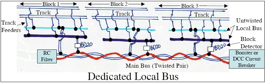
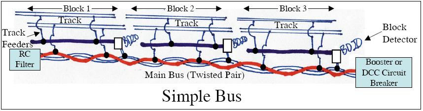
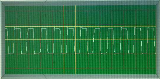
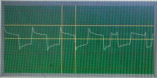
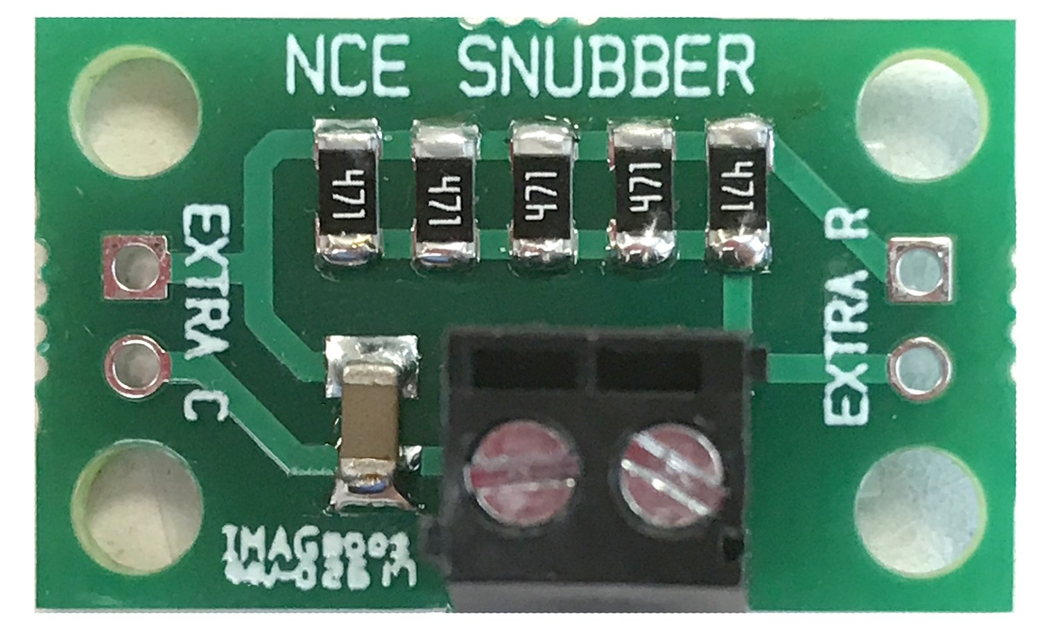
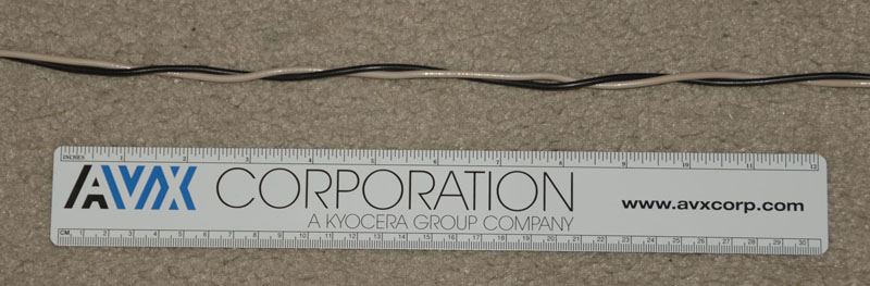
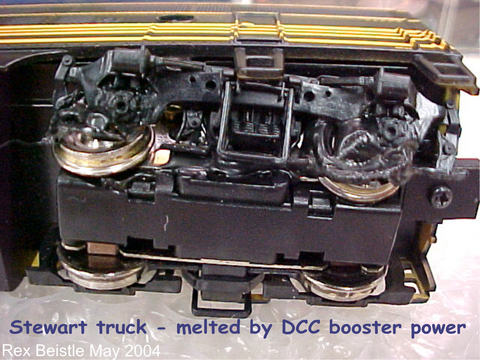


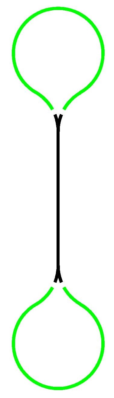
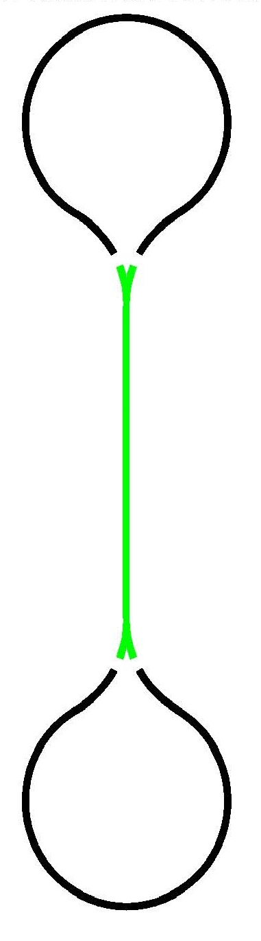
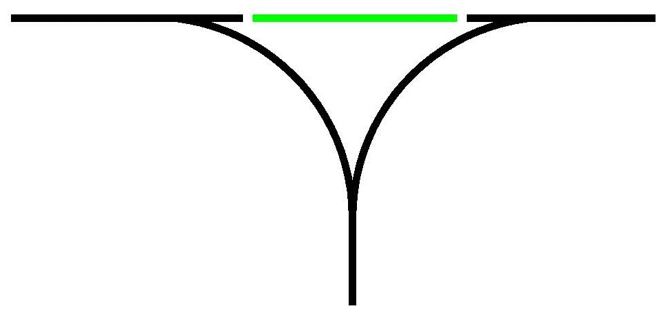
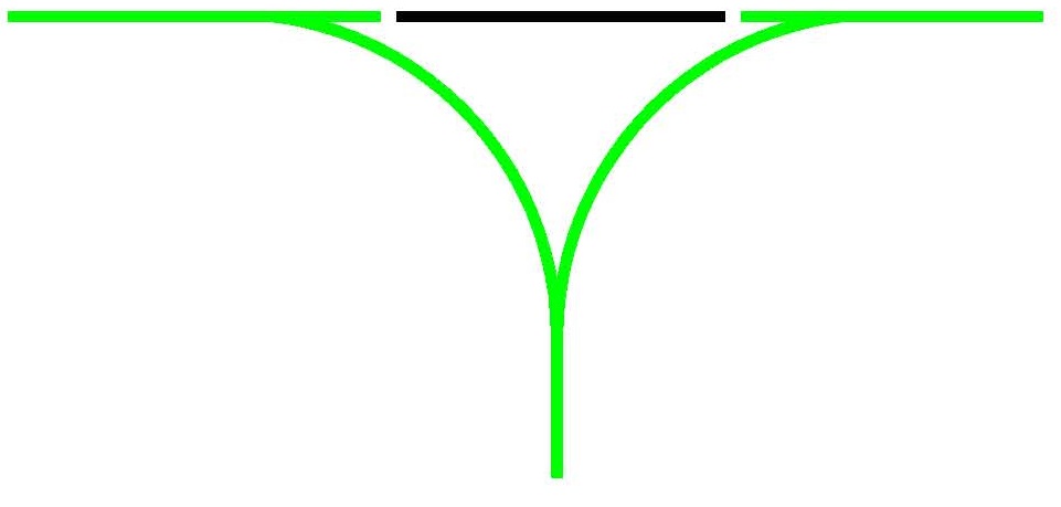
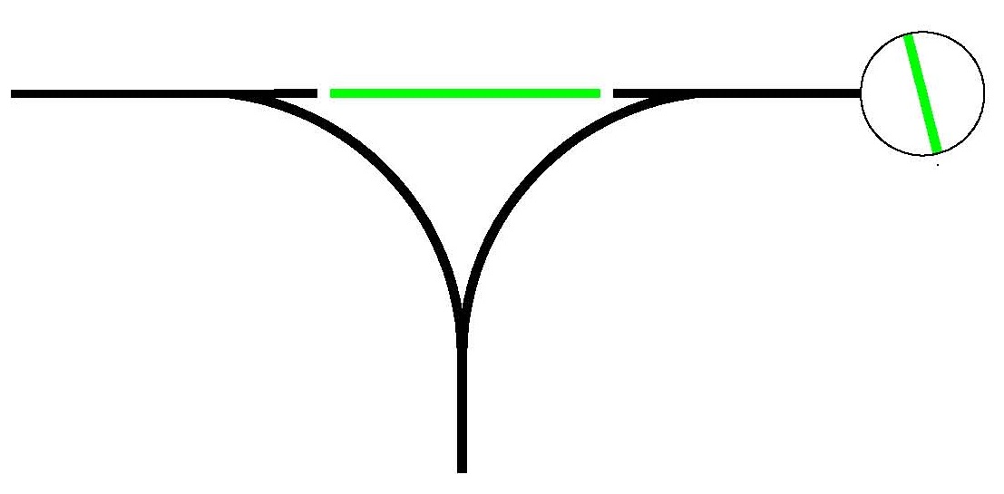
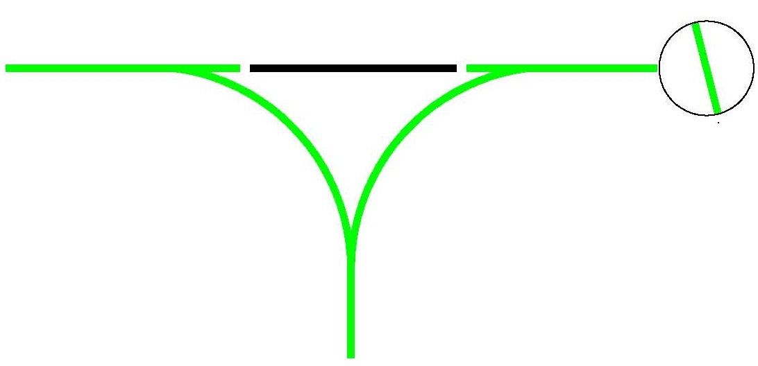
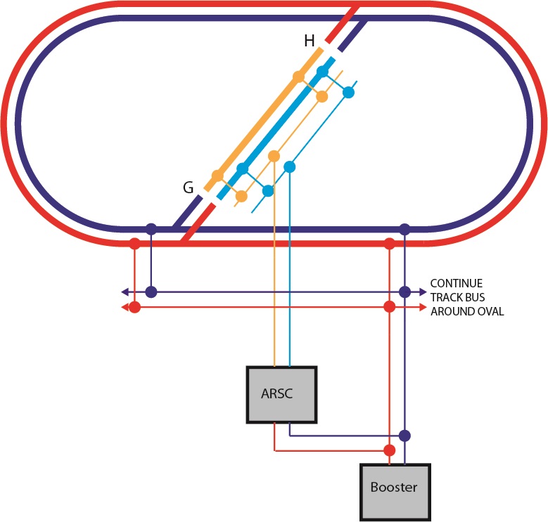
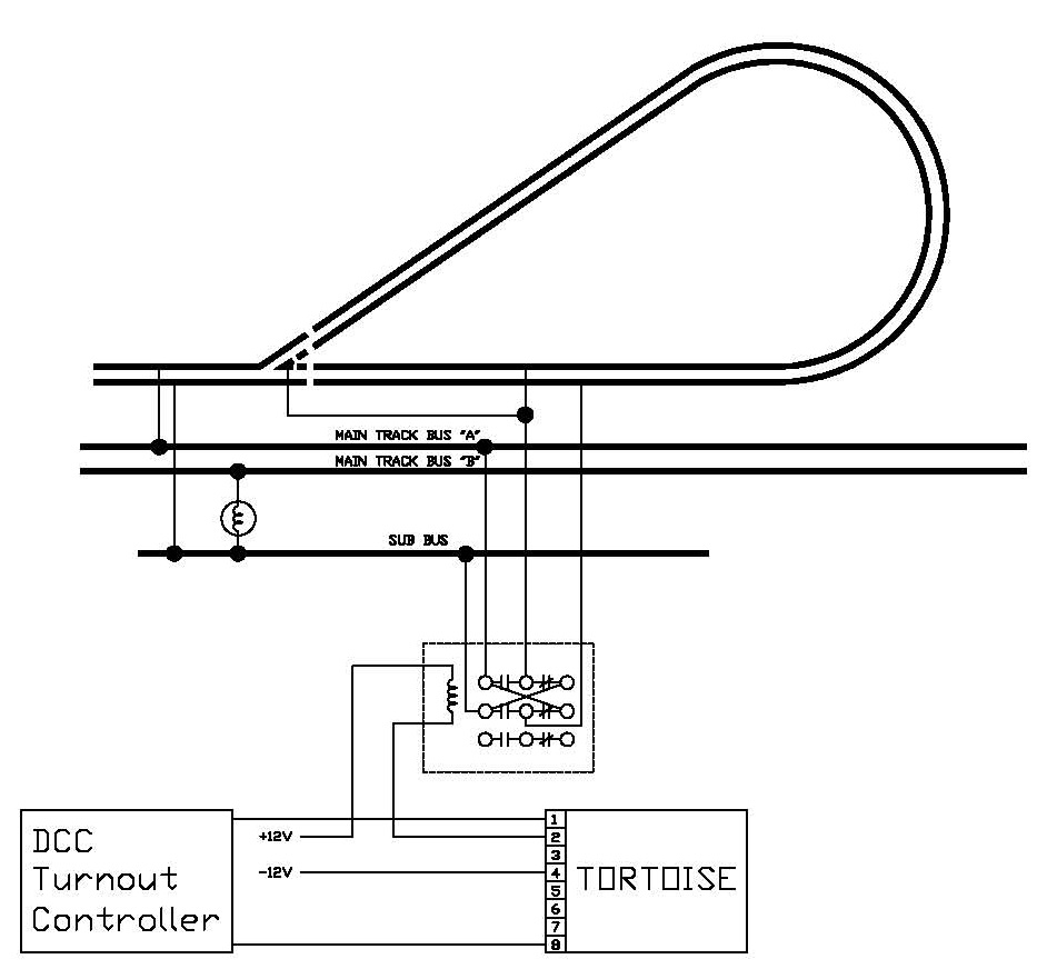
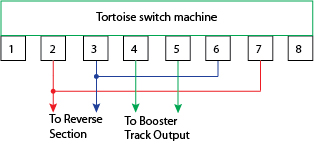
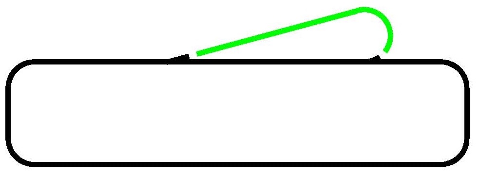
 " E"
" E"