|
||||
Advanced Topics Reading the topics contained in this section are not necessary for the successful implementation of DCC on your layout. These are for the electronically inclined advanced modeler. DCC Waveforms Many thanks to Don Vollrath for providing these 'scope traces. Purpose: It is beyond the scope of this website to train you to read 'scope traces. If you don't understand what you see here, don't worry about it. The advice in this website does not require that you understand this particular webpage. If you are so inclined, a brief tutorial in reading 'scope traces is provided below. Test Set-up:
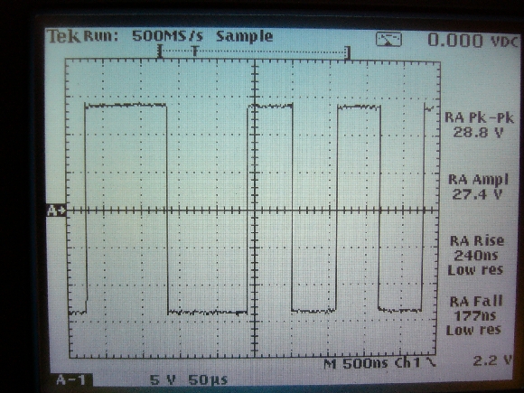
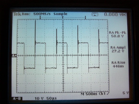
1. Track signal voltage right at booster terminals. Proper amplitude, 28.8Vpp = 14.4 DCC track volts. No ringing. Very abrupt transitions, 240 nano-Seconds rise time, 177 n-Sec fall time. This is a "good, clean" DCC signal.
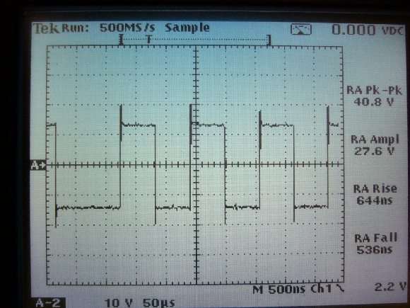
2. Booster signal right at exit of installed EMI filter, located less than 8 inches from booster terminals. Note rise and fall time slowdown (644/536 nano-Sec rise/fall times) but now with visible ringing that increases peak amplitude to +/-20V but not the primary DCC flat-top signal.
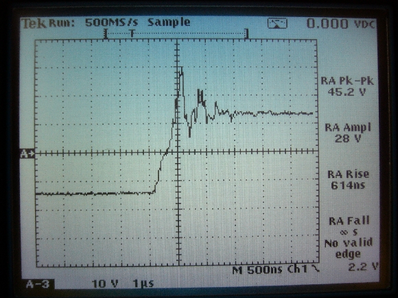
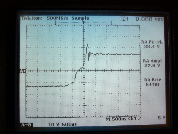
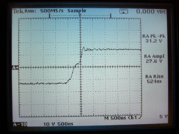
3. Track voltage positive transition 5ft from booster. Ringing now peaks up to 30V, but same basic DCC track voltage.
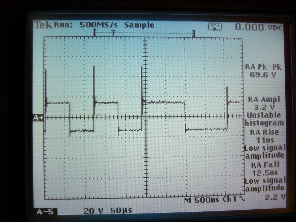
4. DCC unloaded track voltage at end of twisted pair bus 25 feet from booster/EMI filter on open unloaded track. Note severe ringing, now to 50 Vpeak.
5. Close-up of ringing from #4. 25 feet from booster.
Unloaded track.
6. Adjacent track voltage. 25 ft from booster, also unloaded. Very similar to #5.
7. Track voltage of #4 with R/C (0.1 uF, 100 ohms). Note ringing now reduced to 24 Vpeak and damped ringing cycles. Single voltage transition.
8. Same track as 4, 5, & 7, 25ft from booster, but with a decoder equipped loco on the track. Motor ON or OFF or headlight ON or OFF made little difference in signal amplitude or ringing. A constant load of resistor or incandescent lamp did not have the same damping quality as did the loco decoder. How to Read a 'Scope — A very brief introduction (aka 'Scope 101): A 'scope trace shows how voltage changes over time. Voltage is displayed vertically as time passes from left to right. Zero volts is represented by the horizontal dashed line. Positive voltage is above the line. Negative voltage is below the line. Each square is called a division. The bottom display, left of center, says 10V 500nS. That means each vertical division represents 10V and each horizontal division represents the passage of 500nS (500E-9 or 500 billionths of a second). Tin Whiskers Tin whiskers is the growth of fingers or "whiskers" from pure tin surfaces. Usually microscopic in size or at least difficult not to see without magnification, they can short out electronic circuits. If you have had a cell phone, computer, monitor, locomotive decoder or other electronic device mysteriously fail, it just might have been due to a tin whisker. Tin whiskers were blamed on taking out a satellite that suddenly rendered virtually all pagers in the United States inoperable several years ago. Do you remember that? What does a tin whisker look like? There are lots of photos of them on the NASA website. If you promise to come back, take a quick jump to the NASA website to see some at http://nepp.nasa.gov/WHISKER/PHOTOS/INDEX.HTML.
Pure tin affects electronics in two ways. One is the finish on leads of components that were traditionally dipped or plated with tin/lead solder. The second way is the solder used to electrically connect the component onto circuit boards. I have not seen pure tin solder. This is probably because pure tin melts at a significantly higher temperature than tin/lead solder and is too hot for many, if not most, components. The solution is to use tin that is alloyed with metals other than lead to lower the melting point. There are a lot of alloys out there. The one that seems to be the most popular at this time consists of 96.5% tin (Sn), 3% silver (Ag), and 0.5% copper (Cu) and is called SAC 305. Even if SAC 305 is the answer to lead in solder, there is still the issue of pure tin coatings on the leads of components. So it is still possible for all electronic devices with pure tin finishes to grow whiskers. Close to home, your throttles, boosters, command station, and decoders could all fail due to tin whiskers. Is there anything you can do about them? No, not much. Is it possible to fix a device that has failed due to a tin whisker? Maybe. I suppose you could take a stiff bristle brush and try to brush a dead decoder with the hope of breaking loose a whisker (they are delicate) and undoing a short - if the whisker didn't fry the decode in the first place. Then I would vacuum the dead decoder to suck up the now loose whisker to keep it from shorting again. Chances are you have dozens, if not hundreds of whiskers in that dead decoder and you are not likely to be able to see any of them. I can't say whether brushing and vacuuming will definitely work, but if you are going to trash the mysteriously dead decoder anyway it is worth a try. The NASA website has a lot of information on tin whiskers. If you want to learn more about tin whiskers, I encourage you to visit the site. It is located at: http://nepp.nasa.gov/WHISKER . Understanding Voltage Drop contributed by Mark Gurries The current
rating of wires depends on the intended conditions. For model
railroading, we generally cannot tolerate much voltage drop in the wire
which is not even considered a problem at 120VAC.
|
Copyright by Allan Gartner 1996 - 2010 © All rights reserved. You may print this for your own, personal, non-commercial use. Non-commercial, non-personal reproduction may be requested by visiting www.WiringForDCC.com/writeme.htm . All users, commercial and non-commercial, may link only to this site at www.WiringForDCC.com. Thanks to all who contribute to this site and the Q&A forum! |