|
||||
Turnout Control
For Information On Wiring turnouts, Go To the Section On Wiring Turnouts. For Introduction to Turnout Control Options, Go to DCC for Beginners. For DCC Products that Control Turnouts, Go to First Looks.
SUGGESTION #14-2: Use DCC Controlled Turnouts and Eliminate Control Panels! Call me a gadget hound, but this is one of my big attractions to DCC — you don't need any control panels! Or at least not as many. Wiring is the second most time consuming aspect of building a model railroad. DCC controlled turnouts offers money and time saved not buying switches, indicators, wood, and plastic to build control panels. It also eliminates the need to crowd isles with control panels. How do you know what the address is for a turnout? You could put a track diagram on the facia with address numbers. You could also put numbers on the track facing up. I have seen this done by a DC layout where they didn't want to build an elaborate control panel. It worked much better and was much less obtrusive than you would initially think. If you have between-the-rail magnets, this idea will probably appeal to you almost immediately. My H&X is being built without a panel and will locate the numbers between the rails as well as try out other ideas. By using routing, a dispatcher can control which mainline turnouts operators can directly operate. To prevent operators from throwing a turnout, the dispatcher turns off the route. When the route is on, the operator controls the route. The route in turn sends the real address of the turnout a command to move. The cost per turnout is as little as $6 per turnout. From that, you need to subtract the cost of control panel components. I am electrically controlling only mainline, hidden, and hard-to-reach turnouts. All others will be manual ground throws — just like the prototype.
INFORMATION: Methods of Controlling Turnouts There are many ways to control your turnouts on a DCC layout. Here is a list of some of them. While this list has Digitrax specific items, many of the other manufacturers have similar products. 1. Do it the old fashioned way — the way you would have done it for a typical DC layout. To operate the turnouts using your DCC throttle: 2. Use Digitrax's DS-54, DS-44, or any other DCC-operated turnout module. In most cases, you may use any turnout module regardless of who made your command system — in short, you can mix turnout control modules just as you do locomotive decoders. In a few situations, like using the Digitrax DS-54, there are certain features that can only be used if the module is used with a Digitrax system. To control the turnouts using push buttons or toggle switches: There may be situations where you want turnouts to be both controlled by DCC commands and by push buttons. I have eleven such turnouts on my layout. I want the dispatcher to be able to operate them and I want the local yard crew to be able to operate them. It may be inconvenient for the local yard crew to have to keep entering turnout addresses. So the turnouts that connect the mainline with the yard are operated by push buttons in addition to DCC commands over the network. Here are some of the ways to accomplish this. 3. Use the button inputs on a DS-54 if you are not using them for turnout or block occupancy feedback. There is no provision for turnout position indication. 4. Use a Team Digital SRC-8 route controller. It provides inputs for 8 turnouts, 8 pairs of turnout position indicator LEDs, and 8 routes. Normally you would use this with a turnout control module like the DS-54, DS-44, or any other turnout control module (aka auxiliary or stationary decoder). This module is ideal for providing push buttons and indicator lights for DCC operated turnouts. While the SRC-8 is ideally suited for interfacing with control panels, instead of operating LEDs, you can use the module to drive slow-motion switch machines. INFORMATION #14-7: Turnout Controllers: With Feedback or Without. This section is strictly for those wishing to consider DCC methods of turnout feedback. If you are going to have a control panel with LED's, you need not read this section. You can wire it the same way you always have — which is completely independent of DCC — and why it is not covered here. Not everyone needs feedback. Those needing feedback may not need it on every turnout. Where do you need it? I have it on all mainline turnouts for the dispatcher and any hidden turnouts I may be desperate enough to install. It will cost you substantially more, so you may decide to live without it. You can always go with the old fashioned method of lights on a control panel. If you want feedback, you will probably have to go to a turnout or accessory decoder from the manufacturer of your DCC system. An example of such a controller is the Digitrax DS-54. Your cost per turnout will be about $15 per turnout. Those not requiring feedback see section 14-8 below.
SUGGESTION #14-3: Attention Modular Clubs: DCC Controlled Panels Are Especially Well Suited to You! You want to operate your module but don't want to deal with the massive problem of interconnection to a master panel? You have modules that can be turned either way. Where do you put a control panel? Consider DCC controlled turnouts. Instantly, you have no problem! No extra wires or interconnects between modules. One turnout controller can control four turnouts.
SUGGESTION #14-4: Using 4-Wire Handset Jacks with Your Switch Machines. From reading other portions of my page, you will note that wires inside phone cords are not my favorite. However, when used as the phone companies intend, they work fine as long as they are assembled correctly. The Digitrax DS-54 uses these. The easiest way to use the phone cords is to simply not cut them in half and try to attach to the delicate wires inside the cord. Buy a 4-wire handset jack that has wires attached to it and plug the other end into the switch machine. It couldn't be easier! Of course, do cut it to the length you need and then put a connector on the other end. Buy the crimping tool and follow the directions carefully. Be very sure that you insert the cable into the connector so that both ends turn out the same. For example, when I hold a connector with the tab up, I see a left most wire is yellow. Yours may be different. Now when you go to insert the cut end into the new connector, hold the tab up and make sure the yellow wire is on your left. Some cables have a ridge on one side. Don't use this as a guide! You will find to get the yellow wire on the left side, you will have to flip the cable over. If you are questioning your sanity and mine at this point, that's okay — I gave it a lot of thought, too, before deciding it was indeed the right thing to do. Using the 4-wire jacks from Digikey, the colored pigtails correspond to Digitrax's ordering. No, Digitrax and Digikey are not related! Just solder the pigtail ends to your favorite switch machine. Using an adhesive like Liquid Nails or Walther's Goo to glue the 4-pin telephone handset jack to the side of the switch machine or bracket. This will give you a convenient to use assembly. Switch machines have never been so easy to install. Enjoy!
SUGGESTION: Automatic Balloon Track Control Contributed by Don Vollrath Here is a method of using a DCC Auto-Reverser to control the polarity of a simple balloon type reversing loop and also control the turnout. The polarity of the reversing track and turnout will flip to the correct position as trains near the exit. Trains entering from the mainline will run through the loop in alternating directions. An auxiliary relay senses reversing track polarity and controls the turnout motor.
DIRECTIONS: Start with an insulated frog type turnout. A DCC Friendly turnout
is ideal. The length of fixed polarity track from frog to the reverse loop isolating gaps (A & B) may be extended to ensure that the turnout is completely thrown before the train enters the turnout.
Stationary Decoders with Positive Commons (Digitrax stationary address decoders and maybe others.): The Digitrax stationary address decoders use a positive common, rather than the more conventional negative common, for its input signals. If you are using their product with switches, just wire as shown in their manuals. Note that the ground or negative lead of your power source only goes to the sensor's negative or common lead. If you have multiple sensors to use with the stationary decoder, you may. Just hook additional sensors' supply and ground connections to the power supply shown here as a "wallwart" (wall-mounted plug-in power supply).
Thanks to Brad Glass for drawing this schematic. If you use a third-party (non Digitrax) block sensor that has a negative common, you will wire it as shown above and again, you will need to trigger on an open condition.
SUGGESTION: How to Provide Turnout Position Indication See the circuit in the new section on signaling.
SUGGESTION #14-5: Use Slow Motion Switch Machines. Slow motion switch machines are the rage in modern model railroading. Most modelers prefer them due to their more prototypical switching action. I generally have a difficult time getting the old under the table twin coil type switch machines to operate my turnout properly. I just can't seem to get those linkages set right. I find the slow motion switch machines are almost effortless to install. I also find their switch contacts for signaling, power routing the frog, and DCC feedback to be more reliable and easier to hook up than those on use-with-any-rail-switch twin coil machines.
Advanced Slow-Motion Switchmachine Configurations: The following has been contributed by Don Vollrath I use multiple LED indicators and switch machine hook-ups to serve various purposes. Here is a small tutorial session on how to connect toggle switches, power supplies & LED indicators to Tortoise switch machines. The notes may also apply to other brands of stall motors. The Tortoise switch machine motors push the track switch throw-bar in one direction then 'stall out'. You can remove power and the motor will usually stay in place. There is no harm in leaving it energized as long as the voltage across the motor is 12V or less. At 12V, about 10 ma of current will flow. The electrical connections must be able to reverse the voltage & current to the motor in order to throw the switch the other way. a. Multiple controls for a single slo-mo motor
with series indicators.
b. Multiple controls for a single slo-mo motor with
parallel indicators.
c. Multiple slo-mo motors for a double crossover.
d. Multiple slo-mo motors for a double crossover with
multiple controls. e. Controlling slo-mo motors with SPDT switches.
f. Diode matrix control of slo-mo motors for
yard throats.
Developing diode matrix logic.
g. Indicators for diode matrix control of slo-mo motors.
h: Multiple controls for a diode matrix.
i. Triple-voltage power supply for use with diode matrixes.
j: Using your DCC track power to operate your slo-mo
motors.
There is one catch to using your DCC track power to operate your turnouts. If a short develops as a result of the slo-mo motor's operation, everything will stop and you will not be able to get it going again. If you want to operate your slo-mo motors from DCC, consider using a dedicated booster for that purpose. For more on this application, click here. - Allan.
Configuring a Digitrax DS-54 for Slo-Motion Switchmachines: Some Digitrax throttles, like the DT100, display the position of the selected turnout. The benchwork under your layout may dictate the orientation of your switch machine. So you may have to swap the two wires going to the motor. You will notice that the two resistors have the same value. So you do not need to swap the resistors should you need to swap the wires. The feedback switch is not required by Digitrax. Configuring Your DS-54: Suggested CV Values for the DS-54
Follow this sequence to program the above CV's in
your DS-54.
SUGGESTION #14-8: Simple, Low-Cost Slow-Motion Motors Controllers. I don't advocate the use of phone cable when the Switchmaster or Torquemaster motor and Rix Rax II bracket is used with a Digitrax DS-44 or the CVP AD4 accessory decoder because what I am about to tell you is so simple. NCE and no doubt, others have or are coming out with simple, low cost turnout controllers. The following discussion probably covers everything that is or will be available as they will no doubt fall into one of the three categories below. None of these types provide feedback. Use something like the Digitrax DS-54 if you need feedback. Fully Assembled and Ready to Use: The NCE isn't as inexpensive as the Digitrax unit, but it's not too much more (per turnout), and best of all, already comes with screw terminals to connect to your layout wiring. It won't be as compact controlling a lot of turnouts as I describe for the DS-44 below, but it's all ready to go and worth serious thought. If your time is valuable and a few more dollars per turnout doesn't bother you, than a turnout controller like this one is the way to go. If you have a lot of turnouts to control and space is tight, then consider the Digitrax DS-44. Fully Assembled but Needs a Little More Robustness: The Digitrax DS-44 is the lowest cost per turnout, but is not designed to be used under a layout. I find that mounting it to a circuit board and small screw terminals that solder to the circuit board increase its robustness - the wiring is very frail for under layouts. Use some Walthers' Goo to glue the decoder to the circuit board on top of the current limiting resistors if you install them on this circuit board. You can get three of the DS-44's on one terminal strip and will give you compact control of 12 turnouts. See the Radio Shack parts listed in the Getting Electronic Parts section. Kits or Assembled: The CVP AD4 requires the installation of two jumpers - since you are not using the high power option. Take one of the resistors and install it as one of the jumpers; say the odd numbered ones like J1, J3, J5, and J7. Install jumpers in the even positions J2, J4, J6, and J8. Now all you need to do is run two wires from the AD4 to the motor. R1, R2, and the telephone jack, shown above for the Digitrax DS-54, are not needed. It can't get any simpler than this! Add the frog power routing microswitch and the second microswitch for control panel LED's if you are going to have them. Unfortunately, the connector that is used by the AD4(H), is becoming much more expensive than it was just a few years ago. The kit of the AD4 and the connector are only about $2 less expensive than an assembled DS-44. Mixing Controllers? While any mobile or stationary decoder should work with any DCC system, I have had reliable operation difficulties with the CVP AD4 on my Digitrax equipment. Sometimes it works, sometimes it doesn't. CVP has an excellent reputation and popularity. I'm sure the problem is the mix of equipment I have. If you are going to mix decoders with different DCC systems, it is probably wise to buy only one or two at first and make sure you get the reliable operation you want. More GREAT Information: Tony's Train Exchange has a great comparison that is more complete and timely than I can keep up with as part of huge website. Be sure to check out this GREAT comparison on stationary decoders! Note: Tony has a lot of other great information and comparisons. Be sure to check out his web site. Also, check out the manufacturer's themselves as well as those companies that are listed on the manufacturer's page that are sellers or maintaining websites for manufacturers. These are shown in bold.
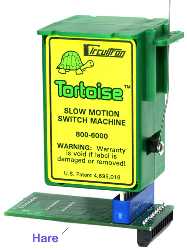
SUGGESTION #14-9: Using Tortoise Switch Machines. The Tortoise is known to occasionally short out the DCC
power while in motion and power routing a frog. Personally, I've not
had this problem. You can: If you want to use Tortoise switch machines I suggest you use DCC friendly turnouts or you may want to avoid power routing the frog. By not power routing the frog, you eliminate the concern about shorting the DCC power or the switch contacts burning up from damaging short circuit currents over time. DCC friendly turnouts have the point, closure, and frog rails already wired to the appropriate stock rail. Therefore you will not have long term trouble getting power from the points as you would with non-DCC friendly turnouts. By using a DCC friendly turnout without power routing the frog, you will have a dead frog. You can minimize your stalling possibilities by using turnouts with the smallest possible dead frog. Also, if your locomotive is not all wheel pick-up, making it so will decrease the likelihood that it will stall on a dead frog. See the section on Wiring turnouts.
SUGGESTION: Controlling a Tortoise - A Decoder Made Just For It!
The manual is pretty clear and succinct. It doesn't leave you confused and full of questions. You can download yourself a copy from the DCC Specialties website. It's worth doing especially if you are contemplating using auto throw, auto reversing and auto entry into a reverse loop. The manual covers these possibilities in detail. If the manual is so good, what is left for me to say? Well, some of you (okay, all of you!) may not want to take the time to read the 16 pages that constitutes the manual. So I'll help you focus on the things that will allow you to implement your Hare without reading the whole manual. I'll also describe some of the features that you might find particularly interesting and note some things you need to know to use those features. First, let me say that while the Hare is loaded with features, you don't have to read the whole manual before you start. Only nerdy engineers like myself read manuals in their entirety! The Hare will work immediately on turnout address #1. If all you want is control a turnout and power route the frog, this is easily accomplished and you can be up and running in literally just a few minutes. Generally, you can implement the use of other features later as you need them. Before we get started, a word about toothpicks. The Hare manual recommends the use of toothpicks to assist in centering up the connector on the Tortoise. I know this seems hoky. Okay, it is hoky. The problem isn't with the Hare. The Hare is using an industry standard connector. If the Tortoise had a connector that was industry standard, the Tortoise might have to be made wider. You probably don't want that. So just use your toothpicks. To get started: Programming a Hare You program switch addresses by using your DCC system to issue turnout control commands. To use the Hare's advanced features, you will also have to program a few CVs. These are programmed in OPS mode. At no time do you use your DCC system's "programming track" or other programming modes. As the Hare manual indicates, you cannot read back CVs in OPS mode. So I suggest you keep a log of what you program into your Hares. Also, since the Hare is not a locomotive, you cannot select it like a locomotive. If you are familiar with OPS mode programming, you need to select a locomotive. So what do you do? You select a locomotive you do not have on your model railroad like 9997. The Hare, when in OPS programming mode, will simply accept OPS mode commands. How do you select which Hare receives OPS mode commands if a Hare will accept any OPS mode command? This is accomplished by using a programming mode jumper on the Hare. When you program the Hare's base turnout address, just put the Hare in programming mode and send it a turnout address with your DCC system. If you want to use route capability, then send it up to 13 more turnout commands. More on route programming coming up. To use these features: Power Routing a Frog with the Hare This can be as simple as hooking up one wire from your frog to the Hare. It depends on how you are going to use your Hare. If you will be powering your Hare from the same booster as the track above it, then you can use the simple wire frog powering hook-up. If you plan to use auto throw (and auto return), you have no choice but to use the simple wire hook-up. If you try to use your Hare with a different booster and you try to use auto throw, you could blow your booster's output(s). To use this very simple hook-up, you need to be very sure of one thing. Your turnouts must not short the track power as the turnout throws. If your track is shorted as the turnout moves, the booster will shut down and the Tortoise will stop. You will be in effect, stuck in this shorted state. If you have a good size layout like me, you may be using a separate booster to operate your turnouts. This has the advantage of operating turnouts that tend to short briefly as the turnout changes position. With a separate booster, the turnout keeps moving and thereby clears the short. If you wired your layout this way, you can use the Hare to power route your frog from the local track bus and corresponding booster. There is one catch. If you use a separate booster to power your Hare, you will not be able to use the Hare's auto throw feature.
To power route a "solid frog" or Peco Electrofrog
when your Hare is powered from your track bus:
To power route a "insulated frog" or Peco
Insulfrog when your Hare is powered from your track bus: Larry Maier of DCC Specialties adds: "J1-3 and J1-4 are
also used to route power (via the DIP switch) to either isolated rail
sections (insulfrog) or the frog (electrofrog) even
if you don't want to use auto throw. This makes the switch operation
more reliable than with the contacts supplied within the switch." If using a dedicated booster to power your turnout controllers: I don't know how many of you are using separate boosters to power your turnout controllers, so I'll just briefly describe what you need to do. If there is interest, let me know and I will provide a diagram. All you have to do it is set all of the Hare's option switches (S1) to OFF to use the Tortoise's contacts. J5 on the Hare provides the Tortoise's contacts for use in power routing. You can buy screw terminal contacts from DCC Specialties or Digikey. (p/n ED1520-ND). Radio Shack sells solder in screw terminals but they are spaced a little differently and therefore, do not work with the Hare. To power route when your Hare is powered from
a dedicated booster: Auto Throw and Auto Return Auto throw is probably the most interesting feature of the Hare because it will automatically throw the points and allow safe passage should a train be approaching the turnout from the wrong direction. Auto return will automatically return the points to a predetermined position. Using these two features will allow a train to exit a siding and then realign the points for the main line after the train has cleared the siding. Pretty nifty, huh? The Hare uses two trigger rails to activate auto throw. To look at the diagram in the instruction manual, you might think that the trigger rails are located very close to the frog. How can this be? The Tortoise is a slow-motion switch machine after all and it takes some time to flip the points. Right you are. If you read the instruction manual, it makes this point very clearly. The diagram in the instruction manual is simply "not to scale." The trigger rail must be located two seconds away from points. For a passenger train or a fast freight, this is about two feet away from the points. For a coal drag, six inches will do it. If operating passenger trains and coal drags on the same layout, you have some decisions to make. You might have to make your sidings up to four feet longer than your coal drags. Or you might decide that your passenger trains will never take the siding at track speed thereby allowing you to have your trigger rails located closer to your turnouts. The manual also covers a way to extend auto throw trigger rails in limited space. It should be noted that a trigger rail is not powered when the points are not aligned for it. Therefore, if your trigger rail is too long, locomotives will stop on it. The manual recommends that the trigger rail be less than the distance between the power pick-ups of your shortest locomotive. One thing the manual doesn't talk about is what to do when you are using a locomotive that has limited power pick-up. I have Mantua locomotives that do the power pick-up on one side of the engine and the tender picks up from the other rail. I also have some Rivarossi articulateds that pick-up on one side of the lead articulated engine and the rear articulated engine picks up from the other side. In both cases, half the locomotive and tender may be across your trigger rail before the Hare knows it's there. The Hare may just be your incentive to improve the power pick-up on these locomotives. In the mean time, it is something you must think about. You may have to locate your trigger rail six more inches away than if your locomotive had all-wheel power pick-up. Auto return is a new feature that will automatically return the points to a predetermined position after a certain amount of time. Make sure your train has cleared the siding before realigning for the main. You can probably use resistors on your axles of your cars to ensure that the siding is held long enough. Auto disable prevents another approaching train from triggering the opposing rail while a train is leaving a siding. To use these features: Local Manual Control and Dispatcher Mode (Lock) You can use push buttons or a momentary-contact, center-off toggle switch to throw the points manually from a local control panel. The manual inputs override any turnout commands that the Hare might receive over the track bus. This means that a dispatcher lock-out of a turnout is easily accomplished if a center-off toggle is thrown and left in one of the operating positions. I am using JMRI for my control panel and thought it would be great if the Hare offered a soft(ware) dispatcher lock. You may see this in the next release of the Hare and will allow a simple turnout command for JMRI or a dispatcher's throttle that will lock main line turnouts in a particular direction. To use these features: Position Feedback The advertising for the Hare says that the Hare V2 can provide feedback to the Digitrax Loconet, the NCE Cab Bus or the Lens XpressNet. It does not connect to any of these buses directly. The Hare V2 provide optically isolated outputs that provide position feedback outputs. These must be connected to devices that can report position to your favorite bus - DS54, DS64, or Team Digital SRC8 for Digitrax, LR101 for Lenz, or AIU-01 for NCE. If you are using a computer control system that has digital I/O cards, the optically isolated outputs of the Hare V2 can be connected to the inputs on the DIO cards. It should be noted that if any other system should enter the market with position feedback capability, the Hare V2 would likely be able to easily interface to it. To use this feature: Connector Mating See below for mating the Hare to the Tortoise.
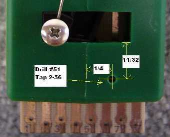
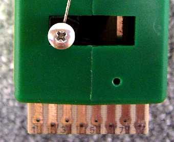
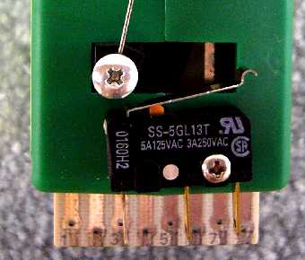
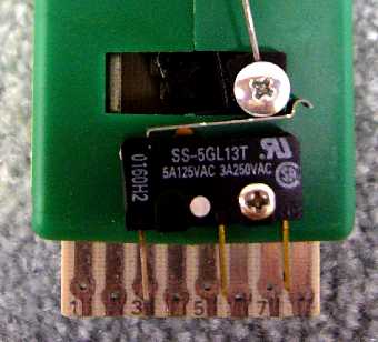
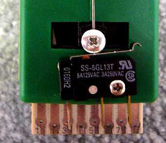
Extra Switch Contacts for Your Tortoise by Don Vollrath An Omron miniature snap switch, SS-5GL13T (5 amp), or SS-10GL13T (10 amp) from Digi-Key fits nicely on the front of a Tortoise motor. These switches have a long operating lever and 110 x 20 quick connect tabs. Carefully drill & tap hole in the Tortoise shell as shown. Place one large drop of polyurethane "Gorilla" glue under the snap switch and mount with a 2-56 x 3/8 screw. Adjust the angle of the switch so that it clicks ON/OFF as the Tortoise movement traverses through the center of travel. If you immediately mount the unit onto the layout, you have several hours to adjust the snap switch to 'click' just as the throw bar of the turnout is in mid position.
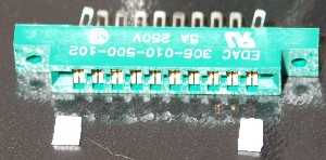
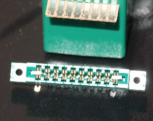
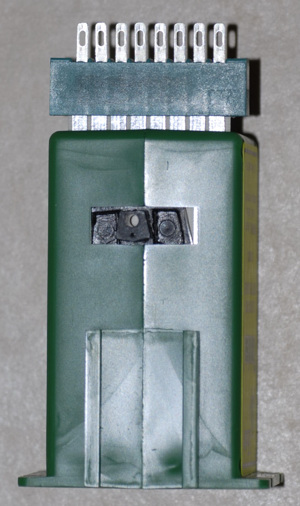
Do You Really Want to Use a Connector? Tortoises are well known for being very reliable. Also, there is no connector made that fits the Tortoise snugly. This means you may not get a permanent, electrically good, connection. Therefore, you should consider NOT using a connector at all. Yes, solder your wires directly to the Tortoise. These things so rarely ever go bad that not using a connector and having to cut the wires some day is a low risk. Connector for Tortoise 09/14/2021 I recently purchased some new Tortoises and noticed that the tan connector on the bottom the Tortoise was now green. Circuitron made a recent change; a change that was for the better. Most notably, the board is now wider and fits industry standard connectors without spacers. (The information below is for legacy Tortoise users.) Note, there has been at least one supplier that made a connector that fit the old Tortoise. It will not fit the new Tortoises.
Legacy Information:
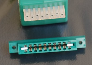
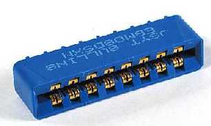
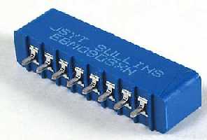
You can also buy blue 8 pin connectors from Traintek and green 8 pin connectors from Bill's Trains and Track. These don't need the outermost solder tabs bent. Both connectors are still just a little too wide for the Tortoise contacts. You will need to center up the connector on the Tortoise or you may short the contacts on the Tortoise. Or glue in a piece of toothpick or narrow pieces of styrene into the connector as above into both sides of the connector. The blue connector does not have solder loops on it. You will need to a solder a straight piece of wire onto it. You will need a third hand to hold the wire.
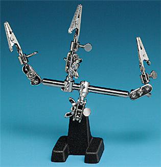
Micro-Mark Third Hand Go to my section on soldering to learn more about this device.
The green connector has solder loops on it.
RECOMENDATION #2-14: Using A Separate Booster for DCC Controlled Turnouts. Use a completely separate booster (more if you have a huge layout) for controlling your turnouts with DCC stationary decoders. The reason is simple. If the turnout stationary decoder is powered by your track bus, and the movement of the turnout shorts out your track bus, the movement of the turnout will stop. With your turnout no longer moving, your short will not go away. A separate booster for your turnouts will not be affected by a brief short to the track directly above that is on a different booster. While this is a good idea, see the section on track regarding bus feeder lengths greater than 30'. You will need to twist your bus wires between your stationary decoders. You will also need to terminate your bus ends. As a way of saving money, you could use the booster from somewhere else in the room to power your stationary decoders. Example: If the room is divided into two halves and you have two boosters, the booster that powers the track on the left half of the room could also control the stationary decoders on the right have of the room. And of course, the booster that powers the track on the right half, could control the stationary decoders on the left half. This could get confusing; use this economy measure only if you can't afford a separate booster to control your turnout stationary decoders. In case you are the slightest bit confused, I am talking about the stationary decoders powering the switch machines. The track is track, whether it be on a turnout or not.
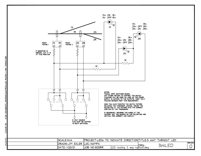
Track Selection Indicator for Three-Way Turnouts Contributed by James Exler, jimXexler@hotmail.com This circuit provides an indication for the one of three tracks coming out of a three-way turnout, like the Peco three-way turnout. The circuit is for use with slow-motion switch machines.
|
|
|||||||||||||||||||||||||||||||||||||||||||||||||||||||||||||||||||||||||||||||||||||||||||||||||||||||||||||||||||||||||||||||||||
Copyright by Allan Gartner 1996 - 2022 © All rights reserved. You may print this for your own, personal, non-commercial use. Non-commercial, non-personal reproduction may be requested by visiting www.WiringForDCC.com/writeme.htm. All users, commercial and non-commercial, may link only to this site at www.WiringForDCC.com. Thanks to all who contribute to this site and the Q&A forum! |