|
||||
|
Sound Thankfully, train sound modules have finally evolved to the point where they sound like trains. No more will I have to worry about the neighbors calling the SPCA or the child abuse hotline due to unearthly noises emanating from my home. Fortunately, there are a number of excellent sounding modules on the market today. Sound Decoder Installation Tips for Specific Locomotives: All sound installation write ups are now listed in Locomotive Installation Notes.
INFORMATION 11-1: Through the Rail Sound Systems DCC is a form of AC. If you have a sound system that transmits the sound through the rails, I doubt that it will work. If you have a locomotive equipped to receive sound from your system, you can try putting it on a track hooked up to a DCC system. Be ready to yank it off the track. The noise could be horrendous and might damage your speaker! Don't worry about hooking up your sound system to track that is wired for DCC. For this little experiment, all you need is a track with DCC on it. The purpose of this little test is to see how your sound receivers will react to DCC signals. If anything from a buzz, squeal, or other hideous noise, I'd say you are out of luck using your current system with DCC. Also, check with your sound system manufacturer. Ask them if their system can work with DCC. They may not know themselves. But they should be able to give you an idea how comfortable they are about having their system attached to another that is generating high frequency AC signals.
SUGGESTION 11-2: Consider Putting the Sound Decoder in the Locomotive, Rather than the Tender. This suggestion applies only to sound decoders that also supply motor and headlight power. Sound decoders that generate sound only are probably better off in the tender. To be sure, read the following discussion. Without a second thought, the sound decoder goes in the tender, right? If the sound module goes in the tender, the following wires cross between the locomotive and tender:
If the sound module goes in the locomotive, the following wires cross between the locomotive and tender:
There's the things to think about. Now you can make the decision that is right for you. Putting it in the locomotive assumes there is space in your locomotive and you feel it is adequately weighted.
SUGGESTION 11-3a: You May Just Want to Go With Throttle-Sensitive Chuff and Skip Synchronized Chuff If you don't have a locomotive with a chuff synchronizing bar built in, this suggestion may be for you. If you have such a bar, go ahead and give it a try. I've tried magnet synched chuff and adding a wiper synched chuff. Neither are 100% reliable. Apparently optically synched chuff isn't 100% either. Given this, I'm not willing to mess with synchronized very much. Steve at Throttle Up! says their experience is that you can't tell if it's synchronized over 5-6 scale mph. On the plus side, synchronized chuff is capable of reproducing wheel slippage if it occurs. Just something to think about. Look at your engine and think about how much trouble it is going to be. If it isn't too bad, try it. If you really want synchronized chuff, go for it! It's your train! Just realize it might get frustrating and be prepared to be patient. SUGGESTION 11-3b: When Not to Use Synchronized Chuff Since writing the above, I've installed a lot of sound
units. There are definitely locomotives that it is not worth the
trouble of installing chuff sync discs. Furthermore, there are
locomotives where trouble down the road could develop. I do not
waste my time considering a chuff sync disc for a locomotive that has
any of the below listed designs. 1. In HO, if the electrical pick-up is from a plunger that rides on the inside of the tire, I do not use a chuff sync disc. Don't get me wrong, I like locomotives with this design. But unless you can keep the plunger from riding on the chuff disc, you will have impaired your locomotives ability to draw power from the track. Down the road, the plunger may wear through the chuff sync disc rendering it ruined. Many Rivarossi locomotives have this design. They also have very few wheels picking up track power. You definitely don't want to interfere with track power pick up! In G scale, it may be possible to use a smaller chuff disc and avoid rubbing by the plunger. 2. Locomotives in any scale where the wheels have sufficient play that the inside of the driver can rub against the drive housing. This also includes locos that have such little clearance that if a chuff disk was present, it would rub on the housing. This design technique is used to enable a locomotive to negotiate a tighter curve than it would otherwise be able to do. Again, I'm not faulting this design technique. I shudder to think how many of my locomotives would not be able to negotiate my curves should they not have some of this designed into them. But again, this design is counter to the long life of a chuff disc. This problem is a common one ranging from Rivarossi in
HO to LGB in G. The new Proto 2000 2-8-8-2 does not have so much
play that this problem is created and I will therefore install a chuff
sync disk on it. Do not put a chuff disc on a driver that is not used for electrical pick up. I tried this to avoid the above plunger electrical pick-up situation. As I feared, less than ideal electrical contact caused false chuffing. Having a chuff sync disc definitely allows the proper chuff rate for the locomotive's speed. It's great when you model starts spinning its wheels and you get to hear it happen! But after you install a dozen or so sound modules, you start asking yourself, how much trouble is that chuff sync disc worth? Real scale modelers will want to cover their eyes and ears on this next one, but garden modelers will know what I'm talking about. Sometimes, you may just want the chuff sync to be much too slow! How can this be, you ask? No, some of you are simply wondering if I have lost my mind. This revelation hit me when setting up my G scale locomotives. Garden railroads are frequently run for a crowd of people standing there awestruck that someone could build a backyard railroad. Or maybe they are just awestruck that someone had that much time, energy, and money to do this. Even if you are running your trains at a speed that is not inappropriate (not too fast), you will find all the chuffs run together. Ride a real steam train highballing it. The chuffs nearly disappear. Garden railroads are mesmerizing because they are highly animated. Hearing chuffs helps that air of animation. So I adjust my LGB moguls to chuff at about 3 chuffs per revolution. The LGB Sumpter Valley Mallet only has 2 chuffs per revolution as built. I decided to leave it that way rather than fix it after I discovered the benefit of "under chuffing." When I want things to be right, I go indoors to my HO layout. I try to get my HO locomotives as close to right as possible. Still, clubs at shows, may find that under chuffing livens up their modular layouts. If you are going to under chuff, there is no point in using a sync disc. Note that you can easily change a CV to take you from prototypical chuffing to under chuffing. You can do this by telling the decoder not to use the sync disc and to use throttle sensitive chuffing. Or you can simply change the chuff rate CV if you are always using throttle sensitive chuff. Just be sure you note what CV value you consider prototypical so that you can put it back the way it should be when the show is over.
RECOMMENDATION 11-5: Watch Those Wire Colors! Many of you are probably buying your decoders from one manufacturer. Buying a sound module may be your first time buying someone else's decoder. When wiring your locomotive and doing the test procedure on sound modules, follow the directions carefully, particularly with respect to wire colors. The NMRA does not say what color speaker wires have to be.
SUGGESTION 11-6: Sound Works Best in Smooth Running Locomotives. This is More Important Than Ever. You have read that to get the best out of a DCC equipped locomotive, you should ensure that it is a good, smooth runner. This is even more important when using momentum. It turns out it is essential with sound. A hesitant locomotive may stall briefly — creating a short and causing the decoder to reset and start the momentum over from the beginning. With sound modules that are throttle sensitive and momentum activated, the problem will be now be reflected in the chuffs for all to hear. Now everyone will know how poorly your locomotive runs. Nobody wants that. So pick a very smooth runner or take the time to make your favorite a first class runner.
This is only the beginning for this section. If you didn't think so much could be written about speakers for HO, check back when a 4 amp polyphonic sound module becomes available for G — real hi-fi speakers in real speaker enclosures — with wheels, of course!
SUGGESTION 11-4: Lots of Small Holes or One Big One for Your Speaker? A single big hole opens your speaker to possibly be poked by something. The smaller holes help protect it.
Speaker Gaskets: What they are and why you need them. A speaker's surround, the part of the speaker that attaches the cone to the speaker cage, is critical to a speaker's ability to move air. After all, moving air is what making loud sounds and good bass is all about. Most small speakers had a surround that clearly didn't allow much travel. (Other things limited their travel as well.) A speaker that is capable of significant travel is something you want. Frequently, speaker frames don't include enough depth for all the travel the speaker may cover. This is because the extra depth is usually provided by the mounting enclosure in some way. DO NOT mount this type of speaker flat against the bottom of your tender. The travel that would otherwise produce great sound will instead hit the bottom of your tender and produces completely unacceptable distortion at any volume. I know. I tried! You will probably never see this travel. It will never go all the way through the tender bottom. But without a little bit of space in front of the cone, it is guaranteed to hit. You may mount the speaker flat against the tender bottom ONLY if you make a large hole in the tender that is big enough for the whole speaker cone to project through. Should you want to do this, use brass screen glued to the underside of the tender to make it difficult for you or a friend (potentially a soon to be ex-friend) to put your finger through it when picking up the tender. DO NOT sandwich the screen between the speaker and the tender bottom on the inside. This would limit the coveted travel and punish you with unpleasant distortion. In the old days, I made a speaker gasket out of a styrene sheet. I used a sheet approx 1/32" (0.8mm) thick. Thinner sheets will probably work, too. I just have not tried anything else. If you try a thinner one and you whistle sounds scratchy, you are hitting bottom and need a thicker sheet. You don't have to make speaker gaskets any more if you don't want to. Soundtraxx now sells speaker gaskets for several of their speakers. If you want to make it, here is a diagram you can print out for one of Soundtraxx's speakers. How do you like the precision that came out of my CAD package? No, you don't have to try building it to such high precision. If you get it to 1/100th of an inch, you are working too hard! :-) After cutting out the cone area, sandwich the gasket between your speaker and tender bottom. Drill a lot of small holes, about 1/'8" (3mm) in the tender bottom BEFORE mounting the speaker and gasket. Resist the temptation to use washers to space your speaker from the tender bottom. For the best bass, and good volume in general, it is important that there be no air gaps around the front of your speaker. Ideally, the tender should be air tight. Air leaks, like where the wires go to the locomotive, could be plugged with a little silicone rubber if you wish. Around the shell and underframe could leak air. For such a small speaker and the resultant small amount of air moved, plugging up small air leaks due to these sources may not be worth the trouble. But big air leaks in the immediate vicinity of the speaker, like using washers to space it up, definitely should be avoided. The styrene gasketis easily cut with a sharp knife. Given the way browsers display and print information from the World Wide Web, the drawing I have provided is probably not exactly the right size. In fact, it is likely not even close. You will have to photocopy my drawing and enlarge or reduce it until it has the dimensions I have specified on the drawing. If anything, make it a little too big; definitely not too small. I was quite happy with the performance of this speaker when used singly. I saw no real need to hook additional speakers together in any of the serial or parallel combinations I have covered in this web page. I had to trim down the sides a bit of the speaker to fit it into my SP 4449 Daylight. I just used a motor tool.
INFORMATION 11-7: General Info on Speakers: More, Bigger, Bass, Volume, & Distortion. You have a fair number of choices with speakers. First let me say that one 1" speaker with a 1 watt amplifier will produce more than enough noise to get you and the locomotive thrown out of the house within the first few hours. Be sure to catch it before the first bounce — which may mean diving for it onto the pavement. You might want to don some arm and knee pads in preparation of this emergency rescue need. Check with your favorite goalie. Under the right conditions discussed below, more speakers or a bigger one may buy you several things: more bass, more volume, and less distortion. Bass is helped by more speaker cone surface area. Volume can be too, as a larger speaker may be more efficient. Distortion is generally caused by the speaker being overdriven. This is generally referred to as clipping. The volume control is set too high and the amplifier is delivering more power than the speaker can handle. It is a nasty buzzing sound imparted to your harmonious train whistle. That's how it manifests itself on my system. If you have it, it will be very noticeable. Don't get hung up about clipping distortion. You will either have it or not. Try one speaker in your locomotive (tender) or temporarily put it in a box about the same size as your locomotive (tender) and set it to the volume you desire. Then go from there. While reading the following information, key in on the phrase for a given volume setting. This is a very important phrase. It's a condition for the comparison of two speaker set ups. If you change the volume setting between the two speaker set ups, then the comparison I will be discussing won't be true. By the same token, changing the volume, either up or down, may give you a benefit that I will discuss. So watch for a given volume setting and also watch for me to mention changing the volume to get some new benefit. Here's a chart that summarizes the speaker arrangements below. 1 is best. 5 is least.
* This assumes that you can turn the volume setting up high enough to achieve this. If you are using 1 or 2 speakers in series and the volume is already all the way up or close to it, 3 speakers won't work any better than what you already have. Baffles: What are They? Why Do I Need One? If you are not an audiophile (a person who loves hi-fi sound) you are probably wondering what a baffle is and why you need one? I thought it would be helpful if you knew the answer to these questions. It is not necessary. So if you want, you can skip to the text after the diagram below. I'll try to make it very simple if you want to read along. Below is an unbaffled speaker. It just a speaker sitting on a table or dangling by its wires. As the speaker cone moves forward, it compresses the air in front of it. This is sound you hear. At the same time it compresses the air in front of it, it creates a mild vacuum behind it. This is bad. Some of the sound that leaves the front of the speaker is sucked around to the back — shown by the red circular arrows. The sound that gets sucked around to the back is sound you do not hear. Hence, the speaker is not very loud or efficient. This effect is most pronounced at bass frequencies. The baffled speaker below does not show the sound getting sucked around to the back. All the sound that leaves the front of the speaker is potentially sound you hear; especially at bass frequencies. Now you know why you need a baffle. While we are being a little bit technical, I'll mention that there is an optimum size for a baffle. However, to determine this, you need some parameters of the speaker you want to use called "Thiele-Small parameters." I've never seen these parameters published for miniature non-hi-fi speakers like you will be using for your model trains. As far as size goes, just try to make the biggest speaker enclosure you can reasonably fit into your train. One last note. Baffles aren't always sealed. For our modeling purposes, they will be. Hence, besides calling them baffles, we will call them speaker enclosures.
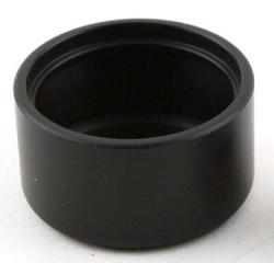
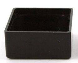
Baffles for Model Railroad Use Generally and simplistically speaking, you want your baffle (speaker enclosure) to be as big as possible. You also want it to be reasonably airtight (to keep the sound from going to the back of the speaker.) Tender Baffles Steam tenders usually make great speaker enclosures. They are large and airtight or can be made airtight. Mount the speaker in the floor facing down, or if not possible, in the coal load and mount the speaker facing up. You will need to drill holes in front of the speaker to let the sound out. For the bottom of the tender, these might be 0.25" (4mm) holes. In the coal load, drill lots of tiny holes. If mounting the speaker under the coal load, make sure the speaker is mounted so that the front is sealed up against the coal load. To do this, mount the speaker flat against a sheet of styrene with a hole or holes cut out of it to let the sound go up through the coal. Whenever making any kind of speaker baffle, I suggest you use sheet styrene 0.04" (1mm) thick or more to keep it from buzzing from the sound. If you have wires leaving your tender through a hole, as long as the hole is much smaller than the speaker, you are probably okay. Just to be sure, you can fill the hole with caulk, RTV, or Walther's Goo. Purchased Baffles (Speaker Enclosures)
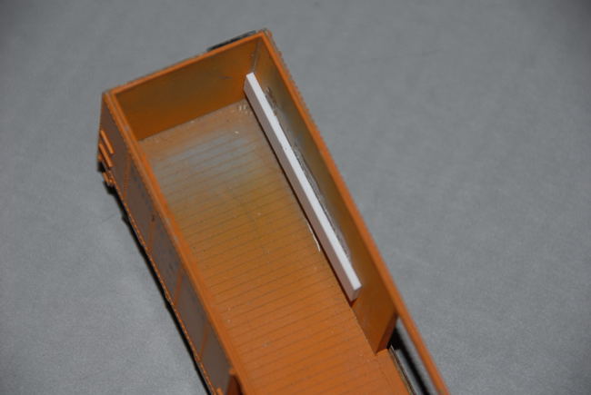
Photos courtesy of Traintek LLC Most diesel locomotives have large open areas for the wheels. They are not airtight and cannot be made so. So you might want to consider a purchased speaker enclosure from your favorite train store. Speaker enclosures you can buy are usually made for specific speakers. You might be able to adapt one that is close with some sheet styrene and Walther's Goo. You will often have to make a hole for the wires to come out. Seal this hole with some Goo. Murphy's Law usually ensures that one dimension or another of the purchased enclosure is too big for your model. If not serious, you can cut the purchased enclosure and make it fit. Again, some 0.04" (1mm) styrene and some Goo should make it fit. In most diesels, space is at a real premium and may be in the wrong place. Using a purchased enclosure may mean that you glue it inside the loco and the air holes may not be facing downward. This is okay, but will muffle some of the highs coming from the speaker and will adversely affecting your horn and bell. Still, you may have no choice. Scratchbuilt Baffles It is usually pretty easy to make your own baffle as you can often use the top, end, and two sides of the locomotive shell to make four of the six sides your enclosure will need. Use 0.04" (1mm) or thicker styrene to make the two sides. Before gluing these pieces in, I suggest you glue two strips to the inside sides of your locomotive. This will give your new sides something to mount to. Without them, it will be a little tricky getting your new enclosure sides to locate exactly where you want them.
Glue two strips to the sides of your shell. These will support the top and side to your baffle.
Test fit your top and side before cutting the speaker hole. Cut your speaker hole in the top. Drill a hole in the side for your speaker wires. Glue your speaker to the "bottom side" of your top. This will put your speaker inside the enclosure when done. Seal all holes and any gaps with Walther's Goo. A Final Note on Speaker Enclosures A hi-fi speaker usually has fiberglass insulation inside of it to prevent the box from resonating and "coloring" the sound. I've seen some purchased enclosures come with a piece of foam for this purpose. I've never tried putting any sound dampening material inside my model enclosures. I'm not too worried about the enclosure resonating and coloring the sound. That's good, because I'm not sure you could get enough sound dampening material inside the enclosure to do you any good. Still, if you want to do this, you can try gluing some cotton balls to the sides of your enclosure.
INFORMATION 11-8: Two Speakers in Parallel. Two speakers placed in parallel will draw more current collectively than one. This will result in an increase in loudness over a single speaker for a given volume setting. As stated earlier, bass will be helped too. If you have clipping distortion, there will be no relative change for a given volume setting since both speakers are working about as hard as they were before. However, since two in parallel are louder than one, if the pair is too loud, you will reduce distortion, perhaps even eliminate it, when you reduce the volume.
INFORMATION 11-9: Two Speakers in Series. Two speakers in series will decrease or eliminate the clipping distortion (depending on how hard it was being overdriven in the first place), probably no noticeable change in bass, and no change in volume for a given volume setting. Each speaker is working half as hard as it was before; which is why distortion went down. To get the same volume as two in parallel, you need to turn the volume up to double the audio output power. With a 1 watt sound module and achieving reasonable and enjoyable volume for my tastes in an HO locomotive, this is easily done. While there is no advantage acoustically to a series connection over a parallel connection, your amplifier will run cooler than two speakers in parallel — perhaps even cooler than a single speaker! Since heat is the nemesis of decoders, and all things electronic, if you desire two speakers and find that you don't need two parallel speakers with the volume full blast, then I suggest you use two speakers in series. Make the wiring temporary if you are uncertain. For those desiring more explanation, here is how it goes. Heat is directly proportional to the amount of current flowing through the amplifier. Two speakers in parallel automatically double the heat loading on the amplifier. So already you see an advantage of series over parallel, but there is more. Heat is also proportional to the voltage drop across the amplifier. The voltage drop to the amplifier is the difference between the voltage that is supplied to the amplifier and the voltage the amplifier is sending to the speaker to produce the desired sound. Let's say the amplifier is being supplied with 12 volts. Let's also say with two speakers in parallel the amp is sending 5 volts to generate the desired sound. The difference is 7 volts. Putting those speakers in series means the amplifier will have to put out 10 volts to get the same volume as the two in parallel. But now the difference is now only 2 volts. This means the amp will run even cooler. Reiterating, if you desire two speakers and find that you don't need two parallel speakers with the volume full blast, then I suggest you use two speakers in series. Also, if you have a decoder that overheats, this is a way to reduce the "heat loading" on the amplifier section. It probably won't help a lot, but every bit helps.
SUGGESTION 11-10: Three Speakers in Parallel. An amplifier does have a finite amount of current it can supply. You are pushing it if you venture to three speakers in parallel. I don't recommend bothering with this configuration.
INFORMATION 11-11: Three Speakers in Series. If clipping distortion is present with two speakers in either series or parallel, three speakers in series should produce a dramatic drop when compared to either two speaker configuration. If you have any volume control left, you may be able to increase your volume.
INFORMATION 11-12: Four Speakers. If you want the most bass, try this combination series-parallel speaker configuration. This has all the advantages of both two speakers in series and two speakers in parallel. It is probably the only practical way to use four speakers.
RECOMMENDATION 11-13: Make Sure Your Speakers Are Phased Correctly. If you are using more than one speaker, you must note the plus and minus signs in the speaker wiring diagrams. If your speakers are not labeled, just pick the same terminal on all speakers as being plus. It doesn't matter which one. Why is this a recommendation, you ask? Because if you don't do this, multiple speakers may be canceling each other out resulting in disappointing sound. They won't be canceling each other out if by chance you did hook them up phased correctly. You have a 50/50 chance of getting this right - or wrong. You paid too much for the sound module to end up being disappointed.
INFORMATION 11-14: Cutting Speakers to Fit. You definitely can cut the sides off speakers to fit. I don't feel I have the fine skills necessary to do a good job. (I can't sign my name neatly much less paint!) Definitely buy some cheap speakers at Radio Shack to practice on. The cut speaker cone must come as close to the sides of the tender or car, but not touch. If it touches, you may get noticeable distortion. If the speaker cone has much of an air gap around it, you will lose a lot of the potential bass you would have gained by opting for a bigger speaker. So get as close as you can.
RECOMMENDATION 11-15: Don't Let Anything Touch the Front of the Speaker. Nothing should interfere with the front of a speaker. Using RTV to mount your speaker, glue the outside edge of the speaker frame to the flat surface with the holes in it - known as a baffle. This is the bottom of your tender or whatever. Do not permit anything to be higher in the middle of the speaker mounting area than it is at the edges. Also, do not permit any RTV ooze into this area where it may contact the moving cone portion of the speaker. All these things may result in distortion, very disappointing volume or nothing at all.
RECOMMENDATION 11-16: Do I Really Have to Glue Throttle Up!'s Chuff Synch Disk to a Block of Wood? Yes. I ran an experiment on it. You definitely need to glue it down before drilling. So as soon as you get your new sound toy, glue it to a block of wood as they suggest in their instructions. Then you will have it when you need it.
SUGGESTION 11-18: Throttle Up! Synchronized Flickering Fire Box . The synchronized firebox flicker works in conjunction with Fireman Freddie shoveling coal. This effect turns on when the shoveling coal sound is heard. The output is off and the bulbs are dark when coal is not being shoveled. If you want a mildly flickering firebox all the time and have it appear to get brighter when shoveling coal, you will need to use one of the function outputs (F1 or F5) for the standard flicker and the other for the synchronized flicker. I'm lazy; I put both in the firebox. The industrious modeler could have one visible through the grate at all times. The other would only be seen though an "open" fire door.
SUGGESTION 11-19: Better Bass From Your Soundtraxx Unit . Throttle Up!'s documentation shows a 50uF capacitor in series with the speaker output. I reasoned that a larger capacitor might improve bass a bit. Throttle Up!'s Steve Dominguez says that up to a 1000uF capacitor can safely be used with their decoders. I use a 1000uF unless I can't fit it in. You can use any capacitor rated 16V or higher. If space is a problem, you will want to use a 16V capacitor as a lower voltage capacitor is smaller. See the section on Parts.
SUGGESTION 11-20: Better Button Arrangements for Your Throttles. Over time, my friends and I have changed our preferred button programming for our Soundtraxx decoders. I've not gone back and changed all my write-ups. And there is no telling this is the final arrangement. Here's what we currently like. The big change is that the bell is now on F4. This is for Digitrax throttles that you would otherwise have to shift for F5 to get the bell. Note that the bell is still on F5 as well. All the things you won't use much are on F5 to F8 - the shifted keys. After each one below, is the hex value to put in the control CV. F1: Controls the flickering firebox. 44
(controls firebox on F1 and F5)
SUGGESTION 11-21: Triggering Your Bell and Whistle. See section in DCC in the Garden for garden railroad applications.
SUGGESTION 11-22: Motorboating? Sound Like a Motorboat? This problem is due to using a 4 ohm, instead of an 8 ohm speaker with sound systems designed for 8 ohm speakers. You are overloading the amplifier. Since the use of a 4 ohm speaker is more likely to happen in garden railroad use, how to deal with this problem is in the section in DCC in the Garden.
SUGGESTION 11-23: Mounting Bell and Whistle Sensors for G-Scale. See the suggestion in the DCC in the Garden section.
IR (Infra-Red) Sensor Triggered Flange Squeal This circuit provides continous flange squeal sounds as a train passes over one or more sensors. This circuit is for particular use with the Miller Models http://www.millermodels.com flange squeal sound module p/n SS683P. Timer triggering is dependent on a sensor that provides a low voltage when a car passes over the sensor and provides a high voltage when there is nothing to detect. Multiple sensors can be ganged to use one sound module if the sensor has a pull down transistor internal to it with an internal pull-up resistor. Such a sensor is made by Don Vollrath DVollrath@magnetek.com The Miller module has a lot of flexibility in how it is used. But as luck would have it, the one mode of flexibility I needed it does not have. The module has an on/off mode and it has a trigger to turn the sound on for one play. Retriggering the module turns it off. What I needed was the ability to handle a string of triggers. As long as the triggers were present, I wanted the sound to keep playing, not stop. When the last car or caboose passes over the sensor one final time, the sound would keep playing for a few seconds and then stop. The sound module, the IR sensor, and the retriggerable timer circuit, will all run on a wide range of DC voltage. I suggest a 9V to 12V DC wall transformer ("wall wart"). The sound module doesn't care which way the DC power is applied to it. So both power inputs are labeled "POWER." You may apply the power to the sound module as you wish. On the other hand, the timer and the IR sensors must have the voltage polarity power properly applied. So follow the circuit diagram below. Changing R1 or C1 will change the amount of time the sound will keep playing after the last time the IR sensor is tripped. With R1 = 100k-ohms and C1=100uF, the sound will keep playing about 12 seconds. If you reduce R1 to say 47k-ohms, the sound will play for about 6 seconds. If you reduce C1 to 47uF, that will also cut the time down to 6 seconds. You can play all sorts of games with the time. Just don't make it too short, or the timer may stop playing the squeal while cars are still passing over the sensor. The equation for setting the time is: T(seconds) = R1 x C1 x 1.1. This circuit is a junk box builder's delight. Except for R1 and C1, none of the values are critical. If you have resistors that are double or half of the values shown, try them. It will probably work. I had everything I needed in my little plastic drawer boxes. I only needed to buy the terminals. C1 is critical in its installed orientation. The capacitor will be labeled as to which terminal is positive and negative. Notice the "+" symbol on the schematic below. The transistors are also critical. Make sure you know which leads are which on the transistor. I have provided a labeled schematic diagram for you. Match it up with the physical diagram on the package you buy.
Transistor shown with its terminals marked Collector, Base, and Emitter.
IR Sensor, Retriggerable Flange Squeal Circuit and Sound Module
Parts List with Radio Shack part numbers. When building the circuit on a perf board, I highly recommend that you print out the circuit schematic above. As you build the circuit, trace it out on the diagram using a highlighter. As you make each new connection, count and verify the connections that are already in place. This way, you will find mistakes you made as you build the circuit and will greatly increase the likelihood that the circuit will work when you are done. This is far easier than building the circuit and finding out it doesn't work when you are done. There is no shame in doing this. I do it. I found a mistake, too. When I was done, the circuit worked on the first try. The sound module comes with a volume control. I think Miller used a "linear-taper" volume control (potentiometer or "pot") instead of an "audio-taper" pot as all the volume control is in about one-quarter of the control's rotation. So don't be surprised if you don't seem to have much control. Enjoy your flange squeals as your trains winds up a steep mountain grade!
Soundtraxx's® Tsunami® SoundCar® Many years ago, I visited Soundtraxx and suggested they make a speed-sensitive clickity-clack. It took a little while, but I finally got my wish and more. It was worth the wait. So when I heard about SoundCar, I didn't waste any time ordering some. For an overview, tips, and a Soundtraxx demo video, go to my "First Look" clinic on the SoundCar. As you will see from my clinic, installation is pretty straight forward so I don't need to say much. I have a few tips to help to avoid damaging anything and some CVs that I used. To get full use out of the SoundCar, download Soundtraxx's user guide and technical reference manual. SoundCar has a generator sound effect that can be used with refridgerator cars and passenger cars. It has lighting effects for lighting passenger cars, marker lights, and fires in potbelly stoves. Your challenge is hiding the SoundCar when used in these applications. See my webpage on using miniature lamps and LEDs when installing these.
CVs I Used I don't want to call these recommended CVs or even suggested. You don't have to use them. These are just the CVs I changed from the defaults. Read my descriptions and if your intended usage is the same as mine, then I just saved you the trouble of determining the CV value you will need. I have included both the decimal and hexadecimal values. Use whichever one you like or your system requires. For computer nerds like myself, the hexadecimal value is easier to determine which bits are set. The CVs are discussed in detail in the Soundtraxx technical reference manual. There are other CVs in the Soundtraxx technical reference manual for adjusting the generator, flat spot probability, volume of individual effects, rate of sounds, number of wheels per car, etc.
For information on power pick-ups for your freight cars, see the next section below.
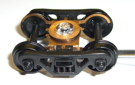
Power Pick-ups for Freight Sound and Light Applications Give yourself a high-five! You found the power pick-up information! I wasn't quite sure where in my website to put this information. So here it is in the sound section. Power pick-up trucks can be obtained from several sources. Athearn: Athearn offers 70-ton, 100-ton, and caboose trucks/late generator. They are all-wheel pick-up.
Athearn's 70-ton HO pick-up trucks
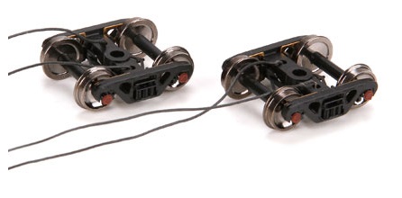
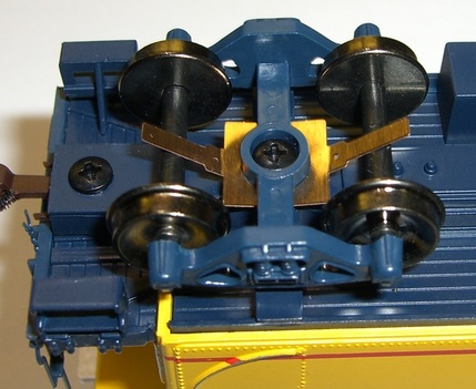
Streamlined Backshop: Streamlined offers two options. Wheel wipers and axle wipers. What's the difference? Rather than try to describe them, here's a picture of the wheel wipers:
Interesting, right? With these, you can have 8 wheel pick-up if you want. You can find them at their website at: http://www.sbs4dcc.com/hoscalewheelwipers.html
Here are the more traditional axle wipers. You can find them at their website at: http://www.sbs4dcc.com/hoscaleaxlewipers.html Ring Engineering: They are available in 33" or 36" wheels for HO. They are only available as roller bearing trucks. My era uses friction bearing trucks. Fortunately, they are not too noticeable and provide a way to identify which cars have SoundCar. The power pick-up trucks are at: http://ringengineering.com/PowerPickUpTruck.htm The matching non-power pick-up trucks are at: http://ringengineering.com/Trucks.htm Compared to a typical freight car axle, there is a form of wiper on the power pick-up trucks so there is a little bit of friction. It can't be helped. How much friction? This will give you some idea: I placed four NMRA-weighted cars on my track with a 2.8% grade. Two of the cars had 1 power pick-up truck each. So of the 8 trucks, 2 had power pick-up trucks. They started to roll a little, but I was able to get them to stay put. But when I came back later, they had all rolled to the bottom of my incline. So there is some friction, but not enough to panic over. If Using All-Wheel Pick-Up: You have a few choices: What you do is up to you. Just in case you are curious, I went with option 3. I just don't recommend option 1 above as you will likely have trouble with intermittent power on dirty track and going across turnouts. If you are using insulated or unpowered frogs, option 1 definitely will not work for you. |
|
Copyright by Allan Gartner 1996 - 2015 © All rights reserved. You may print this for your own, personal, non-commercial use. Non-commercial, non-personal reproduction may be requested by visiting www.WiringForDCC.com/writeme.htm . All users, commercial and non-commercial, may link only to this site at www.WiringForDCC.com. Thanks to all who contribute to this site and the Q&A forum! |