|
|
Walther's/Shinohara Turnouts Do you have a new style, DCC Compatible, Walther's turnout, or the old style? If you don't know how to tell, check out the new DCC Compatible turnout photos. If you turnout doesn't have the features in the photos, then you have the old style and should read this particular web page. SUGGESTION #2-6a: Make a Walther's(Shinohara) Turnout DCC Friendly. Code 83 
Note! I forgot to show the connection of the closure rails to the stock rails. Connect red to red and blue to blue. Making a Walther's (Shinohara) turnout DCC friendly is my most frequently asked question. So here is more detail on making this popular turnout DCC friendly. If you do not like the way I do it, I have included the approach used by one of my readers. You should use a pencil type soldering iron between 25-40 watts. Closer to 40 would be easier. Paint when done. 1. Drill out rivet from the pivot point near the closure rails. Leave the rivet alone on the throw bar. A #48 drill bit works well. Something about 1/16 inch (1.5mm) should work well, too. *Progress in the world of model railroading! Many, if not all, of the Walther's (Shinohara) turnouts now use joiners to attach the points to the closure rails. Steps 2, 3, 5, and 6 can now be omitted! If you have joiners, instead of a pivot, skip 2, 3, 5, and 6. *2. Pry up the metal strip that is under the pivot and connects the two closure rails. Then either cut it in half with a cut-off disk, sheet metal shears, or wire cutters. Using wire cutters to cut this plate is not the best thing for the cutters. Do not use small ones like you would use to wire decoders. You would miss having them sharp. Ones used for house wiring can be used dull - if your's are not dull already. Then using my pencil soldering iron right at the joint of the plate to the rail, pull firmly on what was left of the plate with small pliers. You can get the soldered connection to let go without melting the ties. Note: Be sure to use small or miniature pliers. Larger pliers might draw away too much heat causing the luke warm rail to melt the ties. You want this to be over as quickly as possible. Remove both pieces of the contact plate from the closure rails this way. *3. Unsolder both rails from the pivot mechanism. 4. Unsolder the rails from the throw bar. *5. Trim the spikes and ties underneath the closure rails. Get a joiner on. Mine are very tight and this was not easy. In the process, the joiner might spread where the point rail will slide in. That is fine; you can close it up with pliers before you slide in the point rail. *6. Before putting joiners on the closure rails to hold the point rails, use a motor tool grinder to grind down the ties that will be under the joiner. Failure to do this puts an upward pressure on the joiner and the point rails. It also causes a slight bump under the joiner. Trim the spikes and ties underneath the closure rails. Get a joiner on. Mine are very tight and this was not easy. In the process, the joiner might spread where the point rail will slide in. That is fine; you can close it up with pliers before you slide in the point rail. 7. Remove the points from the throw bar. Down where the throw bar was attached, I ground down the ties that are on either side of the throw bar somewhat so that the points would be making contact with the circuit board and not the ties themselves. I then soldered on the circuit board. If the point rails are touching ties when you solder the new circuit board throw bar, you melt a few ties and the points may not move freely. Solder the circuit board throw bar on. Solder it the same way it was attached to the Shinohara throw bar. I made my circuit board throw bar just under 4/64" wide. See making circuit board throw bars. Better yet, buy them! See where to buy them in 2-19. This shows several things. a) Using joiners to replace the hinge. b) a straight bond. c) a more flexible bond with a loop in it. Note: Some people find their switch machines cannot operate points with additional stiffness (Hankscraft motor driven ones do not have this problem. See section on Parts on obtaining these.) Alternately, it is perfectly fine to drop feeders down from the points to avoid the added stiffness. See the section on wiring bonds for a method of attaching a less springy bond under the turnout.
White "vertical" piece on left of image is actually two pieces of styrene epoxied in after frog was isolated with a Dremel cutting disk. The same thing was done on the right, but it is harder to see. You can see one of the two on the right. The other was blackened with a marker. 10. Electrically isolate the frog by cutting it at the four points indicated in the turnout diagram above. Here is how one of my readers, Gary Feigle enigma@mcs.com, chose to approach the task: 1. Make the rail cuts to isolate the frog first. I made them as close to the frog as I dared. Watch the out for the heat! The action of the Dremel heats the rail enough heat to distort the plastic inside the frog. A little trimming with a dremel fixed the problem for me, but next time I might try holding an ice cube against the frog as I cut the rail. 2. Use a Dremel with a cutting disk to shave off the heads of the rivets on the point rail pivots. 3. Remove the whole point rail piece and the plastic throw bar. 4. The plate under the pivot is not actually glued in, so push up the plate from the bottom of the switch with a thumbtack until it is clear of the plastic. 4A. Ed Schaller, ed@lvrrmodeler.net, suggests: After prying up the plate under the pivot, snip it in half with track cutters. This will make step 5 easier, since you will only need to slide out one rail at a time. 5. Now for the hard part, since the closure rails were cut in step 1, you will find that the closure rails are actually loose. Carefully, slid out the closure rails with the plate still attached. You can push on them from where you made the cut near the frog. Slowly slid one side and then the other, little by little until it comes free. Great care needs to be taken not to damage the ties and especially not those tiny plastic spike heads. 6. Once the closure rails are free, you can easily remove the plate with a soldering iron. You can even get all the solder off by heating it up and wiping it quickly on a sponge. Note: Do not forget which rail is which. They look almost identical, but they are not the same. 7. Now you can test fit your joiner on the unattached closure rail and clear more room for the joiner on the switch. However, do not attach anything to the bottom of the closure rail or on the flange as it may make it too difficult to put the rail back. 7A. Ed further suggests: Before putting the closure rails back, add a dab of epoxy to the ends that will be adjoining the frog to avoid any possibility of rail creep causing a short. File the epoxy to the cross section of the rail if needed. It is a lot easier to do this before sliding the clsure rails back in place. 8. Now we need to put those closure rails back. You must slowly guide the rail back through the spike heads by gently pushing on the sides of the rail to line it up as you pass through each tie plate. Go slow, it is all to easy to shave off those spike heads. You can lose 1 or 2 without much effect, but any more than that and you got real problems. 9. Once you have the rails back in place, the absence of the plate provides enough room for a cut in half code 100 joiner. I used code 100 because it allowed the point rail to swing with complete freedom. Well, that's what I did. For me, it eliminated the tie melting step of trying to remove the pivot plate from the closure rails. I soldered the closure rail end of the joiner without any noticeable melting. I used a 30 watt iron. By the way: I also discovered the necessity of placing small squares of folded paper between the point rails and ties when soldering the point rail to the PC board throw bar. This ensured that the rails had enough clearance to move freely over the tops of the ties. Alternatively, you could place the paper under the throw bar to shim it up. I guess this might not be a problem if your PC board throw bar material is thick enough. Mine was a bit on the thin side. Of course, if it is too thick it may get pinned under the switch when you lay the track. I ran into that too... To avoid a short should someone come into the switch with the points thrown against them, I suggest you use a bulb. See section 2-17 for more on the bulb. See the track wiring section for more information on using light bulbs. How to Wire This Turnout - After Modification to DCC Friendly: This section assumes you have read "How to Wire Turnouts" in the section on turnouts. 1. Connect the frog to your power routing switch or switch machine. 2. Connect your power routing switch or switch machine to your bus as shown in the above drawing. If the locomotive shorts when it goes across the frog, swap the wires that connect your power routing switch or switch machine to your bus. 3. Run a wire from each point rail to the corresponding bus wire as shown in color above. 4. Run a wire from each stock rail to the corresponding bus wire as shown in color above. 5. Run a wire from each closure rail to the corresponding bus wire as shown in color above. 6. Run a wire from each frog rail to the corresponding bus wire as shown in color above. Note: You do not need to use insulated joiners anywhere on this turnout. How to Wire This Turnout - As Is, Out of the Box (not pictured here): This section assumes you have read "How to Wire Turnouts" in the section on turnouts. 1. Connect the frog to your power routing switch or switch machine. 2. Connect your power routing switch or switch machine to your bus as shown in the above drawing. If the locomotive shorts when it goes across the frog, swap the wires that connect your power routing switch or switch machine to your bus. 3. Run a wire from each stock rail to the corresponding bus wire as shown in color above. 4. Place insulating joiners on the two frog rails. Converting Shinohara Turnouts - Another Modeler's Perspective by Denny S. Anspach MD, danspach@macnexus.org Denny Anspach has converted more Shinohara turnouts than I! Here is how he does it and pictures of his work. For some years as I have been drawing upon my cache of new-old-stock,
and "previously-owned" older HO Shinohara code 70 (and some newer 83) turnouts and other special work, I have been diligently converting each and every one of them to be fully "DCC-friendly" as per Allan's
initial admonitions when he first posted his work on the web. This has been a win/win effort ,and I have currently converted about 40 of them over the years. My goal is to have zero-defect DCC trackwork and in the process also able to handle the widest variety of older brass and other ancient locomotives and rolling stock, in addition to newer productions, and these converted handsome turnouts are a major contributor to that goal.
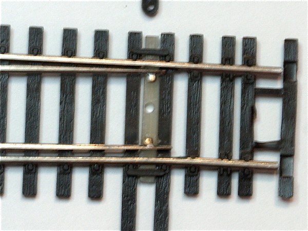
Denny uses a circuit board throwbar without any cladding on it as I show above. Denny attaches his points to the throwbar by using 080 threaded rod. I like this approach as it allows the points to pivot slightly.
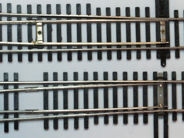
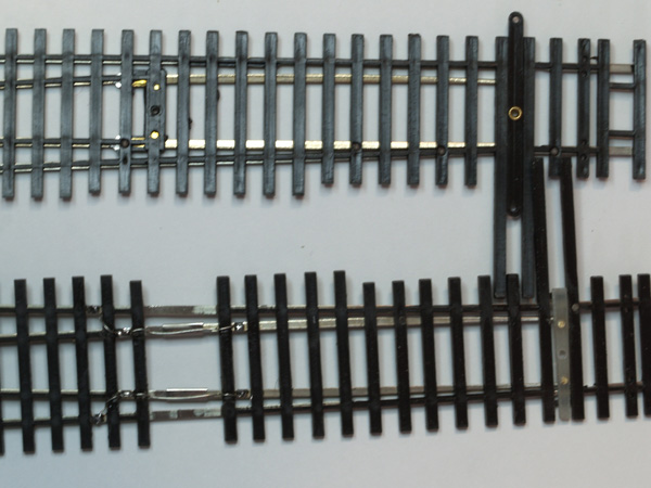
A turnout before and after conversion to DCC Friendliness - top view.
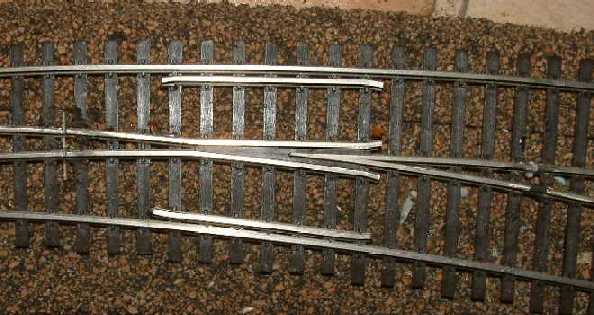
A turnout befoe and after conversion to DCC Friendliness - bottom view.
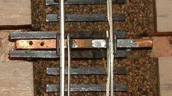
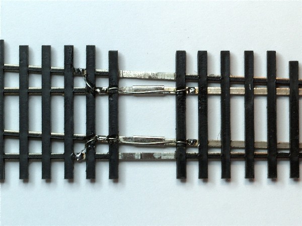
Close-up of bond around joiner used as a hinge for the point rails. Denny puts his bonds on the bottom so they are invisible. You need to use bonds because the rail joiner is intentionally loose - so that it can allow the points to freely move. Barge Cement is a very old product produced in Massachusetts
apparently since the thirties for the shoe repair industry ("soles") .
Ace hardware stores commonly stock it as a very reliable
rubber/contact cement that has a fairly long working time (c. 10-15
minutes), high tack, very high strength and resiliance, but a longer
final setting time (12 hours). It is similar to GOO, but is far easier
to use, far less "stringy", and IMHO is a much better product. The high tack means that things will hold steady in place
while you can do final adjustments. It has also become a common
SUGGESTION #2-6b: Make a Walther's(Shinohara) Double Crossover Turnout DCC Friendly.Code 83 The old styleWalther's (Shinohara) double crossover is similar to one of their individual turnouts with the notable exception that they used rail joiners to connect the point rails to the closure rails. Also, the length of the rails leaving the frog are quite short. Both of these differences will cut in half the amount of effort it takes to make the double crossover DCC friendly. That is a good thing, is it not? Because you have four of them to do! Note: You may notice that two wing rails are shown in red, meaning electrified, and the corresponding other wing rails are in black, meaning non-electrified. That is correct. That is how it is built! Conversion to DCC friendliness is therefore relatively straight forward. 1) Cut both closure rails to isolate them from the frog. Of course, you may want to fill the gap with a piece of styrene and epoxy as you would do with any rail cut. Do this to all four frogs and closure rails. 2) Replace the throw bar with a printed circuit board throw bar. Cut through the copper on the top so that the two point rails are not electrically connected to each other. Do this to all four sets of points. See making circuit board throw bars. Better yet, buy them! See where to buy them in 2-19. 3) Drop feeder from the point rails or solder bonds (jumpers) around the joiners used to pivot the point rails. This is optional, but I highly recommend doing this to ensure long and troublefree life of your double crossover. Conversion time is probably under 15 minutes for the first switch. Probably much less by the time you get to the fourth one. Note the point of crossing. When the turnouts are thrown for crossing, most of the rails in the vicinity of the cross have the correct polarity and those nearby do not have the incorrect polarity - which means a short is possible. There are two points in my drawing where this is not true. I have left these points alone since it would require cuts in the rail and soldering to very short pieces of rail. Whenever soldering rail, deforming the plastic is possible. Short pieces of rail may become misaligned. So by eliminating a possible short, you may be creating a derailment. Therefore, be sure all turnouts contain light bulbs as shown or some other method of localizing the influence of shorts on the rest of your system. Note to manufacturers: I find it interesting that the switches in this double crossover uses joiners to connect the point rails to the closure rails. They are also doing it now to their straight turnouts. With no change in your expensive plastic molds, your turnouts move a big step towards DCC friendliness by using joiners instead of a common pivot. Making A Shinohara Double Crossover DCC Friendly by Steven Baggott, hohum1@tpg.com.au What I have written above is based on my examination of a Shinohara double crossover. I have not actually converted one myself. Steven found that he had to do a few more things to ensure that the crossover was free of shorts. Here is what Steven did to eliminate shorts and make his crossovers DCC Friendly.
Red is right rail 1. Drill out rivet from the pivot point near the closure rails. Leave the rivet alone on the throw bar. A #48 drill bit works well. Something about 1/16 inch (1.5mm) should work well, too. *Progress in the world of model railroading! Many, if not all, of the Walther's (Shinohara) turnouts now use joiners to attach the points to the closure rails. Steps 2, 3, 5, and 6 can now be omitted! If you have joiners, instead of a pivot, skip 2, 3, 5, and 6. *2. Pry up the brass metal strip that is under the pivot and connects the two closure rails. Then either cut it in half with a cut-off disk, sheet metal shears, or wire cutters. Using wire cutters to cut this plate is not the best thing for the cutters. Do not use small ones like you would use to wire decoders. You would miss having them sharp. Ones used for house wiring can be used dull - if yours are not dull already. Then using a pencil soldering iron right at the joint of the plate to the rail, pull firmly on what was left of the plate with small pliers. You can get the soldered connection to let go without melting the ties. Note: Be sure to use small or miniature pliers. Larger pliers might draw away too much heat causing the luke warm rail to melt the ties. You want this to be over as quickly as possible. *3. Unsolder both rails from the pivot mechanism. 4. Unsolder the rails from the throw bar. *5. Trim the spikes and ties underneath the closure rails. Get a joiner on. Mine are very tight and this was not easy. In the process, the joiner might spread where the point rail will slide in. That is fine; you can close it up with pliers before you slide in the point rail. *6. Tip You can cut a rail joiner in half. Too make the hinge Before putting rail joiners on the closure rails to hold the point rails, use a motor tool grinder to grind down the ties that will be under the joiner. Failure to do this puts an upward pressure on the joiner and the point rails. It also causes a slight bump under the joiner. Trim the spikes and ties underneath the closure rails. Get a joiner on. Mine are very tight and this was not easy. In the process, the joiner might spread where the point rail will slide in. That is fine; you can close it up with pliers before you slide in the point rail. 7. Remove the points from the throw bar. Down where the throw bar was attached, I ground down the ties that are on either side of the throw bar somewhat so that the points would be making contact with the circuit board and not the ties themselves. Tip: place a piece of card approx 1mm thick underneath the closure rail either side of throw bar before you solder, this will stop the closure rail from melting the sleepers when it gets hot, plus gives it a bit of clearance so it can operate more freely. Remove the card after soldering. You then soldered on the circuit board. If the point rails are touching the ties when you solder the new circuit board throw bar, you melt a few ties and the points may not move freely. Solder it the same way it was attached to the Shinohara throw bar. I made my circuit board throw bar just under 4/64" wide. File down any excess solder from joints so trains do not de-rail. This completes the modifications to the double cross over. Electrical connections *1.Tip: Select 4 colors of wire That Is Not Your Bus Wire (For Identification Purpose Only) 12 inches will be long enough (300mm). Cut each piece in half 6 inches long (150mm) Long enough to get to a terminal strip. Solder a color wire underneath at the closure rails make sure you solder it to BOTH of the closure rails at the frog you will find the plastic molding missing in the required areas for this. If not cut the plastic away. Solder the wires as close towards the middle of the crossing track as you can. As you will be cutting the rail later, (Not the solder joint).Follow the rail to the other side of the crossing and solder same color on that rail (curved stock rail).close to the crossing side. *2. Repeat process for the other 3 rails *3. Solder 8 Bond wires from the stock rails to the closure rails on all 4 turnouts. (This puts the power back on to the closure rails and makes it LIVE) *4. Cut The 12 rails using a dremel or motor tool with a cutting disc. Close to the sleeper away from the crossing track.3 per turnout 2 at the closure rails / frog. The only reason you are to cut the curved stock rails is to cut all power to the crossing. Otherwise you will have constant power on the crossing on all rails. *5. Join the same colors together and put into a terminal strip 4 separate connections. 1 of each color. Insert the switch wires into the correct terminals. Important Make sure the switch wire from point motor switch goes to the correct color wire you have attached to the frog / closure rail for that turnout. *6. Wire the ON / OFF switch up. That is connected to your point motor. Put the wires from your bus bar to the switch one either side. Making sure you have them the right way around. The switch wire from each turnout switch will then go to the color wires in the terminal strip. Make sure you have the right switch wire going to the correct color wire in terminal strip this will power the frog and one rail in the crossing. Do the same to the other 3 switches and wires. What this will do is change the polarity of the frog so it will be correct and put power thru the crossing and out the other side on one rail only. When the opposite diagonal turnout is thrown the frog polarity is changed as well and puts power on that rail. Which will then give you power on both rails across crossing. Then you can go across the crossing with no shorts. . Have a good look at the drawing before you solder or cut any thing. This Is What I Have Done And It Works For Me. N0 Shorts.
Make a Walther's (Shinohara) 3-Way (Lapped)
Turnout DCC Friendly. by Denny S. Anspach, MD These instructions apply to the code 70 and code 100 turnouts which as of this writing have not been converted to be DCC Friendly. These instructions also apply to the older, non-DCC Friendly turnouts. If your code 83 turnout still has pivot points, you have one of the older turnouts. These instructions apply to you. If you have one of the DCC Friendly turnouts, see the instructions for the new turnouts. This fine HO turnout, produced for many years in codes 70, 83, and 100 is more properly called a lapped turnout (a dominant LH turnout overlapped by a smaller more distant RH turnout). It has two sets of points and three frogs. It is a fine piece of special trackwork, and its use can dramatically decrease the space needed for a yard ladder; and in the same way increase the usable track space gained thereby. Its use with DC analog power has been fairly straightforward (feed the power from the entrance and gap all the exiting rails on each route). However, the higher expectations of electrical reliability with DCC are not met with this wiring alone, and although several proposed “fixes” have been published over the past few years, I have respectfully found them to be ultimately confusing and incomplete, with no report that their applications work in real time. I attempted the basic simplified approach on the bench some years ago, and like others have reported long before me, it worked some, or even most of the time, but the number of shorts experienced was unacceptable on a layout where zero defects was a serious goal. After many weeks of head scratching over the years, and with the more recent help and advice from Max Maginness, Jeff Aley, and Don Vollrath, I now have one of these turnouts modified, installed, and wired in place, and it is working extremely well in a closely-monitored DCC environment with a wide variety of tested locomotives. Similar second and third such turnouts are on the bench ready to install.
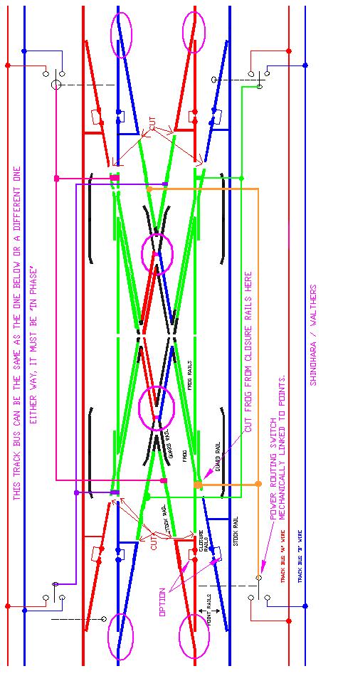
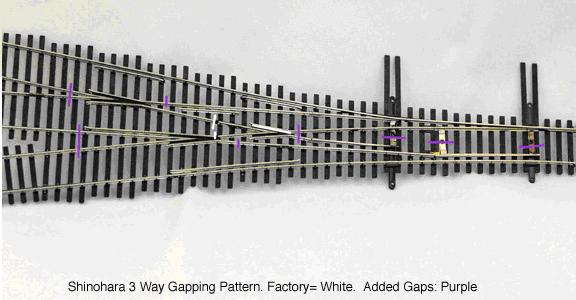
Wiring diagram after you have made your turnout DCC Friendly Allen Gartner’s electrical diagram of how this turnout should be gapped and wired is dead-on accurate and is a reliable basic guide despite his admission that he had no “real” turnout in hand to actually look at. His basic conclusions on wiring are also correct. Where theory and reality do not track exactly is that while some of the gaps he shows are indeed present on the real turnout, other gaps are not, and yet another is hidden within a frog. Gartner’s diagram of how the turnout should be gapped and wired shows: 1. The polarity of the respective N & S point rails be the same as the respective stock rails
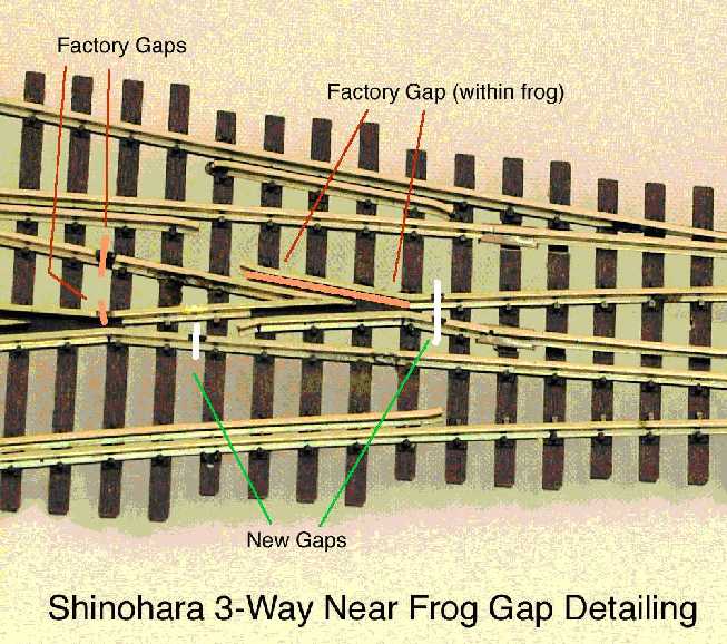
2. Each of the three frogs is isolated and power routed through DPST contacts coupled to the switch motors. There is nothing spectacular nor really different in the diagram from other good long-term well-established principles of DCC turnout modifications. If the reader already knows how to apply these principles, skip the text and just examine the photographs included below, and go at it! For those like myself, always needing help, the following description of methods and cautions may be helpful. Here is what I did: 1. Fully isolated all THREE frogs with gaps in all four directions. Some gaps were already present while others had to be cut. 2. Fully isolated the polarity of the two respective R and two respective L point rails from each other by replacing (discarding) the metal span bars, pivots and throwbars with fully insulated new bars (unclad PCB). 3. Powered the points of the LH turnout is by a Tortoise which also through internal contacts routes power simultaneously to both the first (near) and second (middle) frogs. All leads are through 1156 bulbs. 4. Powered the points of the lapped RH turnout with second Tortoise that routes the power to the third (far) frog just as one would do with a conventional single turnout. 5. Electrically connected each closure rail (both point sets) to respective N or S stock rails with #29 tinned jumper wires under the rails. 6. Electrically connected each point rail to its closure rail with under rail #29 tinned jumper wires across the hinges. 7. Temporary control the Tortoises and routing with two DPDT switches. All three routes (1, 2, 3) work seamlessly, and every combination (RR, LR, LL, RL), of respective turnout positions work without shorting. Cautions and Details: 1. Cutting rail gaps: Use a Dremel tool with a thin diamond saw (I use a high grade saw with a nominal thickness of .010”) at sufficiently high speed that the saw will not have the opportunity to get “hung up”. Stabilize both the tool itself, and your wrist by placing the tool on a thin rubber pad that will neither slide on the rails, nor allow the Dremel tool on top to move. Cut the gaps with a single pass. Glue in styrene fillers. Max Maginness suggests the use of “electronic fish paper” 2. Destabilizing the turnout: Cutting gaps in certain places can leave rail segments unsupported. If such seems possible, stabilize the rails involved with clamps, tape, or even glued “splints”, none removed until the gaps have been cut and the adjacent rails re-supported by the gap being filled with a glued-in styrene strip (ACC or epoxy). I use both .010 and .020 x .060” strips for this purpose. A few swipes with some 400 grit will reduce the thickness, if needed. 3. Gapping metal pivot and throwbars: Replace with PCB board or ties, or other hard insulating material. The best is unclad PCB material with each point rail fastened to the bar independently in pivoting fashion, either to a protruding rotating 0-80 threaded rod (with solder), or to a pin protruding through a hole drilled in the rail flange and then bent over. Soldering directly to PCB board is possible, providing that the fixed geometry that results will allow the point hinges to continue to function compatible with good electrical continuity, and the throw bar sufficient clearance to swing between the headblocks without binding. 4. Hinges: Replace the single metal pivot hinge with two independent rail joiners. 5. Melting ties: Before soldering to rails, clean wax residue (from the molding process) with 90% alcohol. I use fluid rosin for flux. A hot iron (45 watts) with a small spade tip, wielded with a determined “quick-in/quick-out” mindset works well. I use fairly broad based heat sinks made from cheap small metal flea market clamps with the insulating tip covers removed. When soldering to points already in place, I slip pieces of paper between the points and the underlying ties to prevent the heated rails from imprinting, or even embedding into, the underlying ties. Clean up with alcohol and a toothbrush or pipe cleaner. 6. Feeders: Five feeding wires are required. One each to each isolated frog, and one each to each stock rail. I use #24 single strand tinned with the wire tip flattened, bent over, and trimmed like a spike head. Again, use a hot iron- in and out. 7. Jumpers: The wire jumpers within the turnout are best applied from below with the turnout on the bench. This requires some nipping of the supporting styrene structure in places to uncover bare places on the bottom of rails for soldering. There is enough of a surrounding network of support that nipping these out does not alter the turnout’s structural integrity. 8. Planning ahead: Mark very clearly all of the gaps that you want to make very clearly with tape or marking pen, and have clear in your mind what you are about to do, the rationale of why you are doing it, and then do it all in one sitting. There are quite few rails, and in one instance when I was about to begin gapping, my eyes were momentarily diverted, and when I turned back, I neatly cut two gaps…about the wrong frog. I could make use of one gap, but the other one was promptly closed with solder.
Note the metal bars between the rails of both sets of points, and the metal pivot/bar of the right-hand set, all of which require new gapping and/or replacement. This gapping pattern, proper wiring, and power routing of all three frogs will provide a reliable and stable “DCC-friendly” turnout,
Note that gapping the short closure rail (R) requires that the rail be well supported in the process.
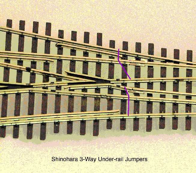
Pattern of wire jumpers between respective N and S closure and stock rails. ©Denny S. Anspach, MD Please do not copy except for personal use. |
|
|
Copyright by Allan Gartner 1996 - 2017 © All rights reserved. You may print this for your own, personal, non-commercial use. Non-commercial, non-personal reproduction may be requested by visiting www.WiringForDCC.com/writeme.htm . All users, commercial and non-commercial, may link only to this site at www.WiringForDCC.com. Thanks to all who contribute to this site and the Q&A forum! |