|
||||
Walthers New DCC Compatible Turnouts Do you have a new style, DCC Compatible, Walthers turnout, or the old style? If you do not know how to tell, check out the new DCC Compatible turnout photos below. If you turnout does not have all* the features in the photos, then you have the old style and should read the web page pertaining to the old style. * "all" is important as Walthers has made some turnouts that used rail joiners on the point rails but the turnout is not otherwise DCC Friendly. How do you know you are buying one of the new DCC compatible turnouts? See below. Walthers DCC Compatible Turnout DCC Friendly Walthers has done it again! They have introduced new turnouts that are DCC Friendly. These turnouts came out in mid 2021. Below is a picture of one. Check out my DCC Currents column in the November 2021 issue of Model Railroader that goes into this turnout in detail.
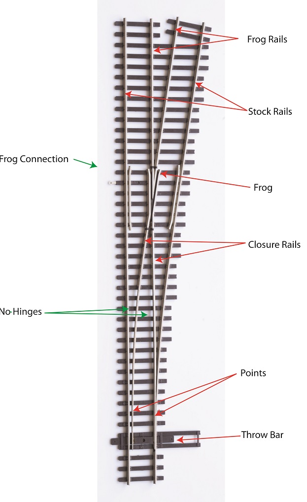
Noteable is that the closure rails and point rails are all one piece with no hinges. I really like that! The frog is about as short as it can be. Some of you may choose to not power it. If you want to power the frog, Walthers has made it easy. There is a terminal out to the side that you can solder you frog wire to. This keeps the heat away from your frog which avoids deforming and ruining the precision alignment required of a frog. If you compare the length of Walthers turnout to a compariable Peco, you will find that the Walthers is longer. Have no fear. The basic turnout is the same length. You will find the frog rails are longer on the Watlthers. If you want, you can shorten them. Just try to avoid shortening them so much that you end up removing the electrical bonds shown below. Why make it longer? I don't know what their motivation was, but in a yard situation where you frequently have a lot of turnouts and previously had really short pices of track you had to add, I think you will find that you don't need to add short pieces of track any more. Nice!
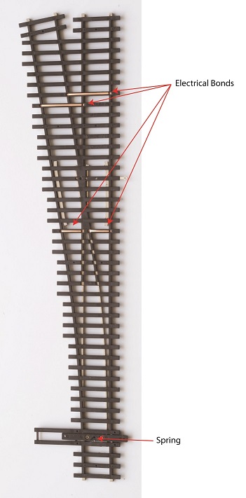
The throw bar has a spring like the Peco turnouts have always had. You can remove it when using the turnout with a switch machine. The bonds on the back of the turnout makes wiring easy. The frog rails are connected to the stock rails and the stock rails are connected to the closure rails. How to Wire This Turnout: This section assumes you have read "How to Wire Turnouts" in the section on turnouts. Couldn't be easier, just: 1. Connect your track bus to the two stock rails. 2. If powering your frog, connect your frog rail to the terminal Walthers provided on the side of the terminal. That's it!
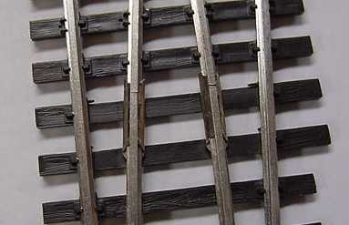
Here is a discussion of the old "new" Walthers turnout that is now discontinued. Walther's has introduced a new line of "DCC Compatible" turnouts. Are they DCC Friendly as defined in this website? In a word: Yes! The pictures below tell the story and highlight the features that make this turnout what we have all been waiting for - a readily available turnout, in the largest variety from any manufacturer, that is DCC Friendly. Code 83 
Photos courtesy of Walter McIntosh
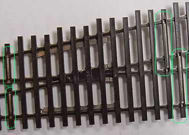
How Do They Look? While this website is dedicated to DCC, as this may be your first opportunity to see these new turnouts, a few words about their appearance are in order. The frog is a favorite among modelers in assessing the detail of turnout. The frog on this turnout isn't as detailed as some cast frogs. But notice that Walthers darkened the area between the rail heads The hinges at the tip of the points are unappealing, but I believe easily resolved. Two pieces of styrene should do the trick. Glue a thick piece of styrene between the hinge points. On top of this piece, glue a wider piece to act as a cap covering the hinges. Paint to match the creosote-colored ties. Using The New Turnout There is not anything you need to do to make this turnout DCC Friendly as defined on this website. You just need to do a few things: 1. Make sure all the bonds on your turnouts
are electrically connected. See above. Fix if necessary.
See below. You need to do one more thing for long, reliable operation. Pick one of the following: a. Attach two wires from your point rails to your buses.
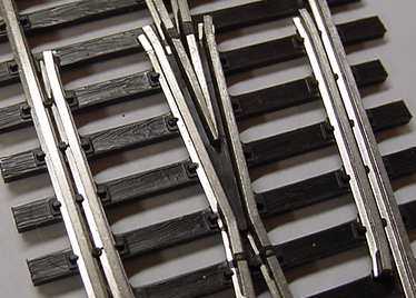
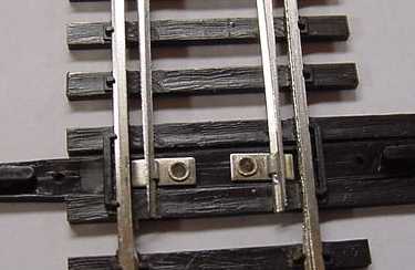
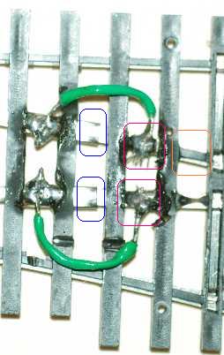
(This is my preference.) OR Above is a pair of bonds soldered across the joiner underneath the turnout. The wire is green so that it would show up easier in the photo. I used #24 AWG stranded wire so that the least amount of springiness would be added to the points. Notice that joiner end (blue highlight) is in the center of the photo. It acts as a hinge. To prevent your points from becoming too stiff, do not solder here. To prepare the turnout for the wire attachments on the right, trim the thin plastic strips (red highlights) from between the ties with a sharp knife. You can see examples of such strips in the photo above between other ties (orange highlight). Do the cutting with the turnout on a table top. Do not hold it and cut as the knife may slip and cut your fingers. While this task is probably best accomplished with a resistance soldering station, I did the above with a 35 Watt pencil soldering iron just to see if it could be done. To solder on the wire using only two hands: How to Wire This Turnout: This section assumes you have read "How to Wire Turnouts" in the section on turnouts. 1. Connect the frog to your power routing switch or switch machine. 2. Connect your power routing switch or switch machine to your bus as shown in the above drawing. If the locomotive shorts when it goes across the frog, swap the wires that connect your power routing switch or switch machine to your bus. 3. Run a wire from each point rail to the corresponding bus wire as shown in color above. 4. Run a wire from each stock rail to the corresponding bus wire as shown in color above. Note: You do not need to use insulated joiners anywhere on this turnout.
Code 70 and code 100 Shinohara turnouts are still non-DCC Friendly as of this writing. Also, you may still have an old code 83 turnout. If it has metal pivots for the points, you have a non-DCC Friendly turnout. For instructions on converting the non-DCC Friendly turnouts to be DCC Friendly, see these instructions.
Double Crossover Tutorial G.T. Galyon has shared his experience with the Walther's/Shinohara double crossovers with this website. Click below on his tutorial on implementing these crossovers. You will need Adobe Reader to read the double crossover tutorial.
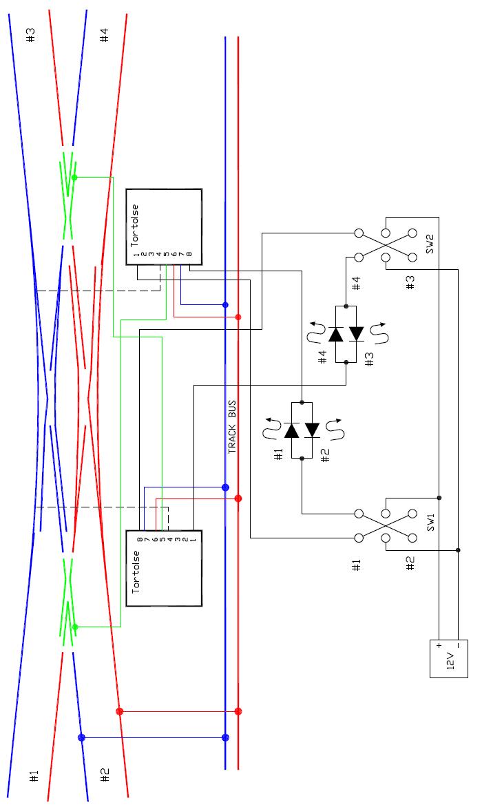
Wiring the Walther's DCC Compatible (Friendly) Double Slip Turnout Thanks to Discount Model Trains, Addison, TX for their assistance. When you first open the box to your new double slip turnout, it can be a bit intimidating. You wonder where you are going to start. Looking at my color-coded version of the turnout shows that it is actually fairly simple. (Some of you are probably wondering, if I consider this simple, you don't want to see complicated! :) It is simple. It is essentially just two turnouts layed one on top of another - the points on the left affect where the train goes on the right and vice versa. You will notice pairs of points connected together with a metal strip and a rivot. If you have read the rest of this website on DCC friendly turnouts, you may be wondering if have a DCC friendly turnout. You do. Look at my diagram for this double-slip. You will notice that the pairs of points that have the metal strip and rivot are at the same polarity. Because of this, you still have a DCC friendly turnout. I've tried to help you out showing you all the wiring you will need including how to wire up Tortoise switch machines. I have also put the toggle switches on the same side of the turnout that they affect. This will aid you in wiring your turnout in your control panel. The only drawback is that the drawing is slightly more complicated as the toggle for the right Tortoise is on the left side of the schematic and vice versa. But by doing what I have done, the toggle switch for tracks 1 and 2 is located near these tracks on your panel. The same goes for the tracks and toggle on the right. While wiring this turnout is simple, there are lot of opportunities to get something swapped. So if you follow my step-by-step instructions and test things out as you go, you should have a successful installation. Another advantage in testing things as you go, is that it allows for some variability in how you install your turnout. For example, I show the Tortoises facing each other. If due to benchwork constraints you can't do this, that's okay. In my instructions below, I will tell you that when you test something things work backwards, I will tell you to swap wires and all will be good.
Read all instructions first so that you know what is coming. Some of your questions will be answered in later steps. Step 1: Install the turnout and Tortoises Wire the blue and red rails to the track bus. You can connect any pair of red and blue track rails to the track bus as they are all interconnected. This turnout uses rail joiners to connect the movable points to the fixed rails. The points get their power through the joiner and by touching the stock rails. This is an understandable construction technique, but less than ideal for long term electrical contact. See photo and text above for adding bond wires to your points. You do not need to attach a bond wire to each point rail, only one bond is needed for each colored pair. As I noted at the beginning, each pair of points has a metal tab connecting them. It is recommended, but not essential, that the Tortoises face each other. Connect the frogs to terminal #5 on the Tortoises. Do not connect terminals #6 & #7 on the Tortises yet. Step 2: Install SW#1 Wire SW#1 to the 12V power supply. The power supply can be a 12V wallwart (wall transformer). It needs to put out DC, but does not need to be regulated.You should have SW#1 mounted in your control panel as well as the two LEDs that go with it. SW#1 and the LEDs will be associated with tracks #1 and #2 as shown. Step 3: Connect SW#1 to Tortoise Temporarily connect the wires from SW#1 to the LEDs and the Tortoise on the right side of the diagram. The Tortoise and the points on the right side should now be operable by SW#1. Don't panic if something is backwards. Manually move the Tortoise mechanism on the left side of the diagram so that the points on the left side of your layout look like my diagram. This will set you up for a movement from track #3. 3a. When SW#1 is set for track #1, you should be able to follow a route from track #3 to track #1. If instead, you find a route from track #3 to track #2, then swap the wires going to the terminals #1 and #8 on the Tortoise on the right. Try again. Once you can follow a route from track #3 to track #1, you can solder the wires for terminals #1 and #8 for the Tortoise on the right side. 3b. Now check your LEDs. The LEDs should correspond to track #1 or track #2 and indicated by the position of your toggle switch and the points as found in 3a. Once you have the LEDs wired properly, you can solder your connections to them. Step 4: Install SW#2 Wire SW#2 to the 12V power supply. SW#2 will operate the Tortoise for tracks #3 and #4 as well as the corresponding LEDs. Step 5: Connect SW#2 to Tortoise Temporarily connect the wires from SW#2 to the LEDs and the Tortoise on the left side of the diagram. The Tortoise and the points on the left side should now be operable by SW#2. Don't panic if something is backwards. 5a. Set SW#1 to track #1 and set SW#2 to track #3. You should not be able to follow a train from track #1 to track #3. If instead the train goes from track #1 to track #4, swap the wires on the left side Tortoise terminals #1 and #8. Try again. You should now be able to follow a train from track #1 to track #3. Flip SW#2 and follow a train from track #1 to track #4. Solder your wires to the Tortoise on the left side. 5b. Test the LEDs for SW#2. The LEDs should light with the corresponding track positions of track #3 and track #4. If the LEDs are operating backwards, swap the wires to the LEDs. Once you have the LEDs corresponding with the toggle switch position, solder the wries to the LEDs. Step 6: Set the frog polarities The easiest way to set frog polarities is to read my section on Getting the Frog Polarity Right on the main turnouts page. Read it and practice on an ordinary turnout so that you can get the routine down. Either install a new turnout or practie on one you already have installed. Remember that the points on the right side of the diagram go with the frog on the left side and vice versa. However, to keep the confusion down, after you connect the alligator clip to a frog, you will touch the other end to the stock rail of the color I indicate. 6a. Connect an alligator clip to the left frog. Temporarily connect terminals #6 and #7 of the right Tortoise to the track bus. Operate SW#1. When SW#1 is set to track #1 and you touch the other end of the alligator clip to a red stock rail, nothing should happen. When you touch the alligator clip to a blue stock rail, you should get a short. If the opposite happened when you touched the alligator clip to the stock rails, swap the temporary connections going to the track bus and try again. Now flip SW#1 to to track #2. Now when you touch the alliagor clip to a blue stock rail, you should not get a short. When you touch the alligator clip to a red stock rail, you should get a short. If everything worked as I indicate here, then make your connections to the track bus and Tortoise terminals #6 and #7 permanent. 6b. Connect an alligator clip to the right frog. Temporarily connect terminals #6 and #7 of the left Tortoise to the track bus. Operate SW#2. When SW#2 is set to track #3 and you touch the other end of the alligator clip to a red stock rail, nothing should happen. When you touch the alligator clip to a blue stock rail, you should get a short. If the opposite happened when you touched the alligator clip to the stock rails, swap the temporary connections going to the track bus and try again. Now flip SW#2 to to track #4. Now when you touch the alliagor clip to a blue stock rail, you should not get a short. When you touch the alligator clip to a red stock rail, you should get a short. If everything worked as I indicate here, then make your connections to the track bus and Tortoise terminals #6 and #7 permanent. You're done! Enjoy your new double slip! Which Turnouts Walthers is Making DCC Compatible: Check the Walthers website for availability and which turnouts will be available DCC Compatible. Skip through to about page 3 and look for the part numbers starting with part number 8801. These are the new DCC Compatible turnouts. How You Know You Are Buying One of the New Turnouts: Walthers is using their existing boxes with a neon-yellow sticker you cannot miss. It says: NOW IMPROVED This is the turnout you want to purchase. The sticker also has the new part numbers on it. Be sure to check their website for availability. As of this writing (3/24/04), not all models of this turnout are yet available.
Check Your Turnouts for Good Electrical Bonds: The bonding straps on the bottom of the turnouts is something new for Walthers. On some of the early production units, these bonding straps are not making good electrical contact. Of the three units I have inspected, only the initial one had a problem. This is provided for the people with the early production units. Here is what to do. 1. Before buying a turnout, check it out electrically in the store. Use the colored diagram above to guide you. All the rails shown in red should be connected together. All the rails shown in blue should be connected together. Use an ohm meter to make sure the various pieces of rail are electrically connected as shown in the diagram. When checking, do not have the points touch the stock rail of the side of the turnout you are checking. This will give you a false positive indication. 2. If you have already bought the turnout or want to buy one and don't mind fixing it, it is fairly easy to do. Just determine which bond is defective and run a wire between the two rails of the defective bond. Or you can drop feeders from the problem rail to the busunderneath your layout. |
|
|
Copyright by Allan Gartner 1996 - 2017 © All rights reserved. You may print this for your own, personal, non-commercial use. Non-commercial, non-personal reproduction may be requested by visiting www.WiringForDCC.com/writeme.htm . All users, commercial and non-commercial, may link only to this site at www.WiringForDCC.com. Thanks to all who contribute to this site and the Q&A forum! |