|
||||
NTRAK Alternate Wiring and Connectors
|
|||||||||||||||||||||||||||||||||||||||||||||||||||||||||||||||||||||||||||||||||||||
|
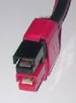
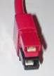
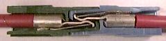
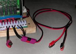
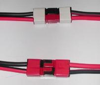
Track Bus: Anderson PP30 “30 Amp Powerpole” red/black pairs. Housings to be stacked vertically using built-in dovetails, hood up, tongue down, black over red on left end of module and red over black on right end (memory aid: “Red-Right”). See figures at far left and right respectively. DC Power Bus: Anderson PP30 red/black pairs. Housings at both ends stacked horizontally using built in dovetails, hood up, tongue down, red on the left, black on the right. Red is DC+, black is DC-. See figure at lower right. |
|
Color Identification: Connector pairs to be marked with tape or paint (red/yellow/blue/white, etc.), or use appropriate colored housings in place of the red housing of each pair (i.e., Yel/Blk, Blu/Blk, Wht/Blk etc.). |
|
|
Connector: The Anderson PP30 Powerpole connector is comprised of a PP15/45 housing and contact a # 1331 contact. The contacts will accommodate 12 to 16 gauge stranded wire.
Contact attachment: Strip wire back approximately 5/16”. Orient contact on wire for proper insertion into housing. Smaller gauge wire may be folded double or triple as necessary. Crimp or solder contact to wire. (For a review of some available crimping tools, see PPcrimp.htm).
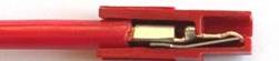
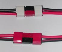
Assembly: Hold housings with hood up and tongue down. Insert wires with contacts attached (barrel up and tip down) into the appropriate connector housings. Push the contacts in until the contact tips “click” over the retaining springs as shown below. If you have difficulty, check for deformation of the contact barrel or excess solder remaining after attachment or excessively thick insulation which may interfere with contact insertion. You may need to trim insulation and/or re-shape or file the contact barrel slightly to get an easy fit. A new, unused contact makes an excellent guide to use as a check after crimping).
|
|
For each Powerpole equipped module or module set, one set of Left End and Right End adapters must be provided. Adapters should be 6” long and color coded with tape, paint or by using colored Powerpole shells in place of the red shell.
Right End Adapters:
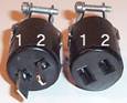
| Track Bus - Powerpole Left End connector (black over red) to CJ male, wide pin (#1) to red, narrow pin (#2) to black), 6” long. DC Power Bus - Powerpole Power Bus connector (red on left, black on right), to CJ male, wide pin (#1) to red, narrow pin (#2) to black). |
 |
|
| Left End Adapters: Track Bus - Powrpole Right End connector (red over black) to CJ female, wide pin (#1) to red, narrow pin (#2) to black). DC Power Bus - Powerpole Power Bus connector (red on left, black on right), to CJ female, wide pin (#1) to red, narrow pin (#2) to black. |
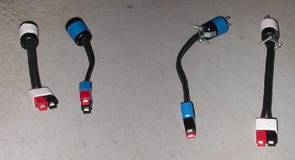
Track Bus and Power Bus Adapters
DC Power Bus and Adapters
Wire: 12-gauge stranded copper. Either black low-voltage lighting wire with a “rib” molded along one conductor, red/black automotive “zip” wire, or speaker wire may be used. Arms of the Y should be no more than 12 inches. Stem of the Y should be at least 4 ft long to to allow connection to a floor mounted booster or throttle.
Connections: Consistent with module Track Bus convention. Red or ribbed wire (front rail) is designated “Rail A”, black or plain wire (rear rail) is “Rail B”.
Connectors: -Arms of Y equipped with one Left End and one Right End Track Bus Powerpole PP30 connector (as described above) for track bus connection. Stem of Y connects to throttle or booster output either directly or via Powerpole connectors mounted vertically, red over black (Y cable end) and black over red (booster/throttle end).
Color Identification: Red/black connector pairs at the stem of the Y should be marked with violet tape or paint, or purple connector housings used in place of the red housing of each pair. No color coding is specified for Y cable arms, as they can connect to any NTRAK line.
 Track Power Feeder Connections |
|
Specifications for Powerpole connectors can be found at the Anderson Power Products Website at http://www.andersonpower.com/products.
30 Amp Anderson Powerpole connectors are typically packaged in red/black sets, although colored housings are also available. The following table lists Anderson part numbers for the various connector parts:
Anderson Powerpole Part Numbers
Housing Color |
Complete |
15-45A |
30A |
|
Red |
1330 |
1327 |
1331 |
|
Black |
1330G4 |
1327G6 |
1331 |
|
Yellow |
1330G11 |
1327G16 |
1331 |
|
Blue |
1330G12 |
1327G8 |
1331 |
|
Green |
1330G2 |
1327G5 |
1331 |
|
Orange |
1330G13 |
1327G17 |
1331 |
|
White |
1330G5 |
1327G17 |
1331 |
|
Purple |
1330G17 |
1327G23 |
1331 |
|
Powerpole connectors are available from a number of sources via the internet, including:
Powerwerx |
||
| Connex Electronics | http://www.connex-electronics.com | |
| Cablexperts | http://www.cablexperts.com | |
| Quicksilver Radio Products | http://www.qsradio.com/DCpower.htm | |
| Hometek | http://www.cheapham.com/page10.html |
Most of these suppliers also stock 12 gauge red/black zip cord, which makes for a clean installation.
Powerpoles are also carried by major industrial electronics distributors, including Newark InOne (http://www.newark.com) and Allied Electronics (http://www.alliedelec.com).
The connector convention described above permits modules to be reversed in place without cross-over wiring or other adapters. This makes reversible corner modules and reversible oNeTRAK modules particularly easy to implement. The figure below shows two standard modules on either side of an outside corner module. Red/black (front rail/rear rail) integrity is maintained in this standard configuration. The photo to the right illustrates the mating connectors.
 Corner Module – Outside (Normal) Configuration |
|
If a module is reversed in place, two left end connectors will be facing each other, as will two right end connectors (similar to a “same sex” standoff with CJs). Unlike CJs, adapters or double terminations are not required, as black will connect to red and red to black, thereby performing the cross-over function and maintaining proper front rail/rear rail integrity (Note: In the case of NTRAK, red and blue line connections must still be swapped, but no adapters are required). The figure below illustrates the same outside corner in its reversed position , showing how front/rear rail connections are maintained, while the right-hand photo below shows the mating connectors for a reversed module..In both cases, the DC Power Bus (white) is not affected.
 Corner Module – Inside (Reversed) Configuration |
|
Copyright by Allan Gartner 1996 - 2010 © All rights reserved. You may print this for your own, personal, non-commercial use. Non-commercial, non-personal reproduction may be requested by visiting www.WiringForDCC.com/writeme.htm . All users, commercial and non-commercial, may link only to this site at www.WiringForDCC.com. Thanks to all who contribute to this site and the Q&A forum! |