|
||||
San Juan Car Co. Turnouts contributed by Steve McKee, smckee@everestkc.net If English isn't your primary language or you just like a lot of how-to pictures, you will like Steve's work. Steve is a perfectionist. He will show you how to make the switch [turnout] DCC friendly, optimize it for perfect operation, and wire it to a Tortoise switch machine.
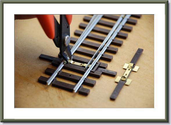
Part I Fine tuning the throw bar.
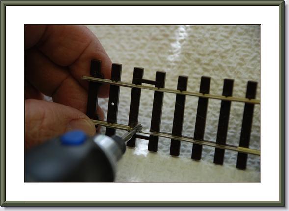
Cutting out the original throwbar.
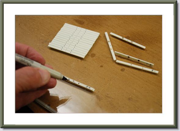
Mark drill spots on Fast Tracks PC board ties. Remove copper clading off of them first.
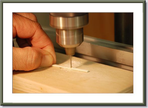
Drilling
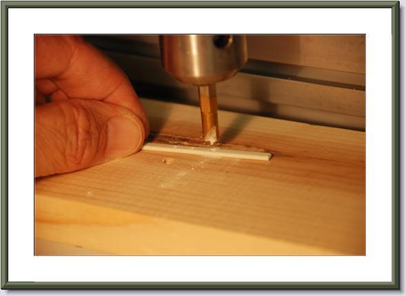
Making pocket for screw head.
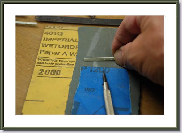
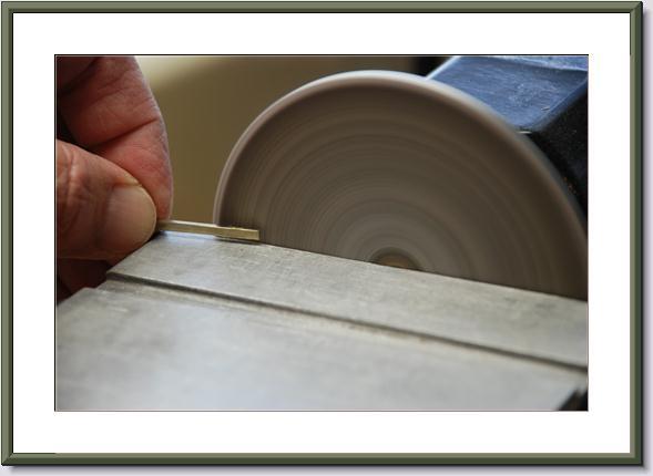
Making edges smooth. Walmart sells fine grit sandpaper in the auto section.
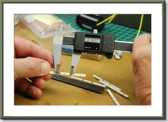
Measured in millimeters.
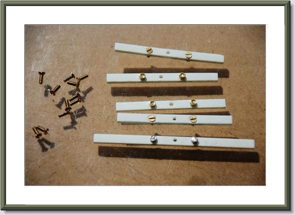
Flat head #80 screw-nuts on PC board ties.
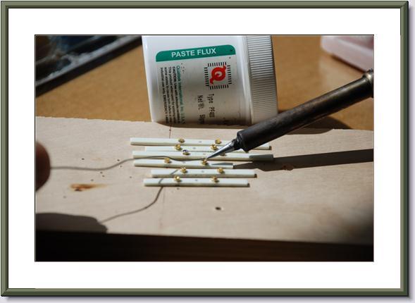
Apply a small amount of solder to keep screws from unscrewing.
Part II Fine tuning the points and stock rails.
Grind slot so rail fits up against outside rail. Sometimes they don't fit right.
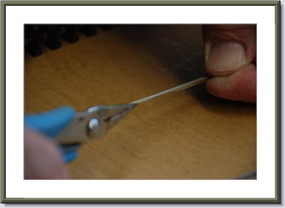
Filing down the point rail to make it thinner on the end where it touches the outside (stock) rail.
Sometimes you have to rebend it to make it fit right.
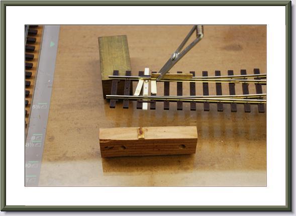
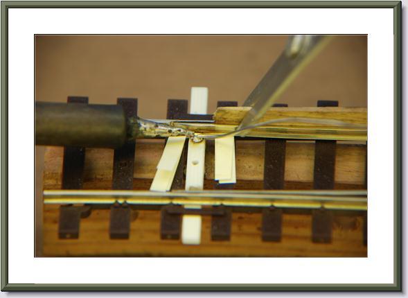
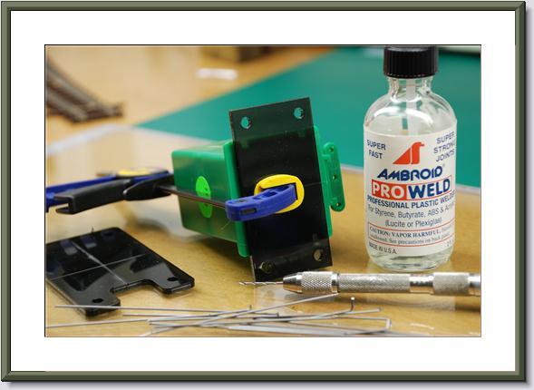
Clamp the point rail to the stock rail while soldering the screw on.
Solder screw to point rail using silver solder from PBL. I also use sponges for heat sinks so to not melt the plastic ties. Use hot solder tip so it heats quickly. I also use solder paste and non rosin silver solder from PBL [Liquid flux should also work very well for this application as it heats quickly and doesn't leave a residue. Liquid flux and silver solder can be obtained from H&N Electronics, http://www.ccis.com/home/hn. If using a soldering pencil, I suggest you use one that is at least 35W or better yet, use a resistance soldering iron. For more information, see the section on soldering. - Allan]
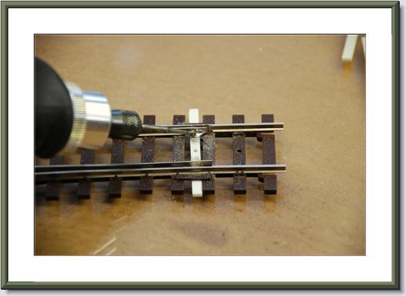
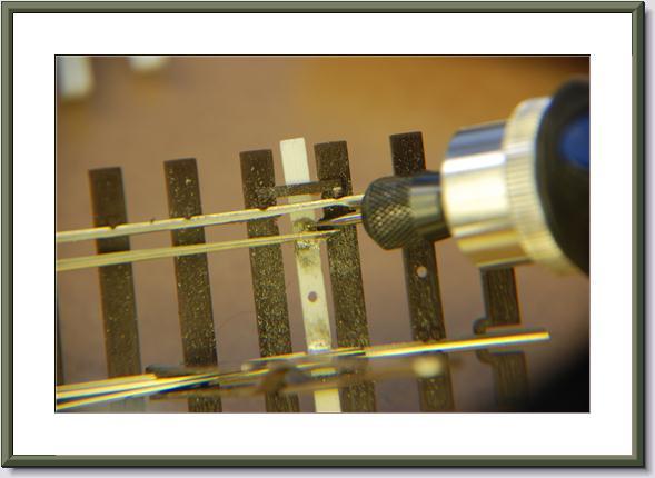
Grind down excess solder.
Using small grinding tool I got from my dentist. Works good on teeth, too.
Part III Making the switch [turnout] DCC ready [friendly].
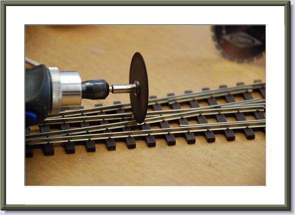
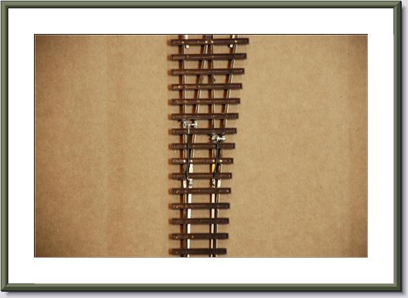
San Juan made the cut above this one but you need to cut here also to isolate the frog.
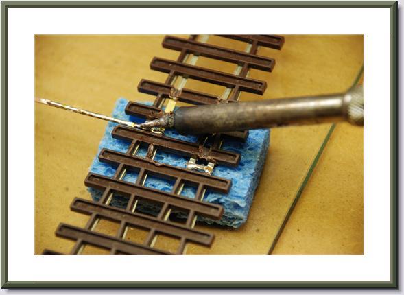
I pre-tin everything to make it easier to solder. It solders quicker that way. This is also where a wire gets soldered in the next step. Notice sponge below track to keep plastic ties from melting.
Solder wire onto these frog connectors which goes to #4 & #5 on the Tortoise switch machine.
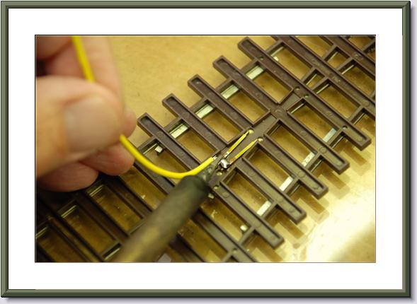
Short piece of wire to inside moving rails so they have power all the time and not just power from touching outisde rail or rail joiner.
Wires soldered to outside rail for better power pickup.
Another picture of how I soldered connections.
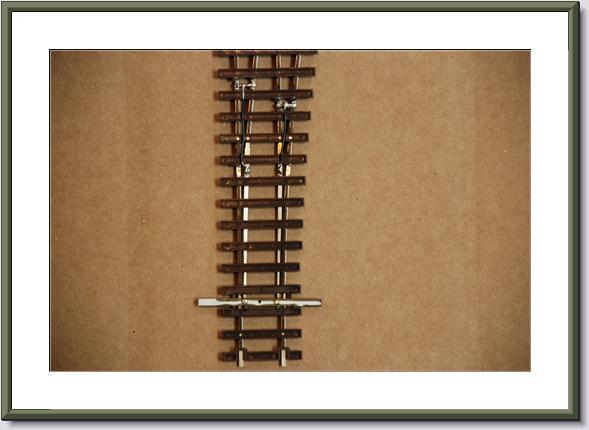
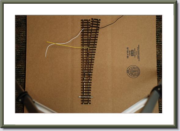
Picture of switch [turnout] with all three wires soldered to it and connecting wires for inside rail. The black and white wires go to the track power bus wire.
Part IV Wiring and Mounting the Tortoise.
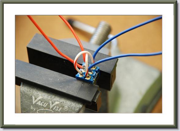
How I wire up the DPDT switch. Note the cross over wires. The blue and orange wires on the center terminals go to the switch machine. The blue and orange wires on the end terminals go to the switch machine power bus.
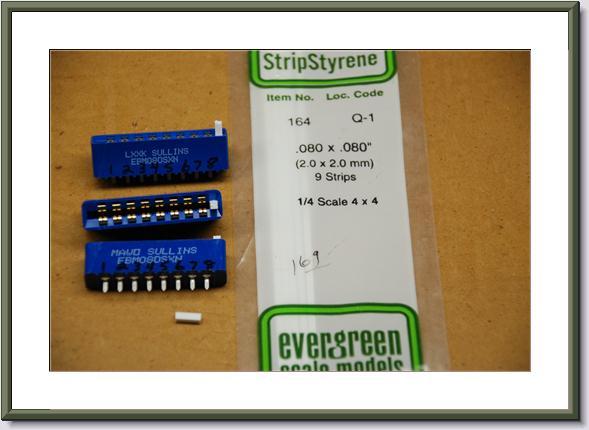
Edge connectors from ModelrRailroadSupply.com [or your favorite Tortoise dealer - Allan] I numbered them from 1 to 8 to match the 1 to 8 on the Tortoise. You have to glue a piece of styrene so the connectors hit the right spot on the Tortoise. [ See Connector for Tortoise http://www.wiringfordcc.com/sw_ctl.htm#a19 - Allan]
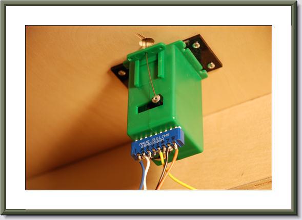
This is how it looks when hooked up. Notice the plastic glued to top of Tortoise. It makes attaching the Tortoise much easier. It was made by Kaw Vally designs and is just plastic with four holes drilled in it. Kaw Vally does laser cutting which made this part easier. Terminals #1 and #8 go to DPDT switch. Terminals #2 and #6 connect together and go to one track power bus wire and #3 and #7 connect together and go to other track power bus wire. Terminals #4 and #5 is the yellow wire that connects to yellow frog wire in switch [turnout] itself. I also use .038 piano wire instead of what comes with the Tortoise. By doing it this way all soldering is done at the work bench except for the track feeder wires.
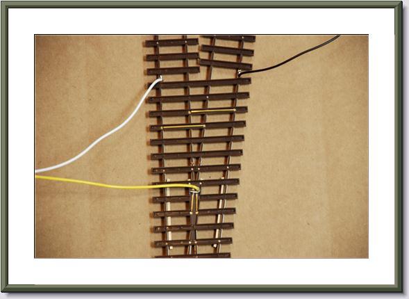
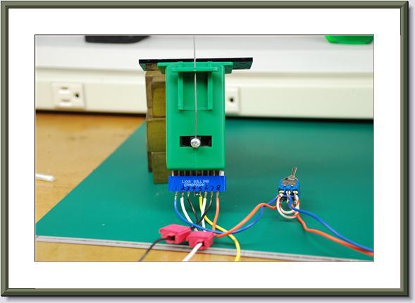
Here is a picture of the whole set up. Orange and blue wire on right go to switch machine power. The black and white go to track power and the yellow goes to frog wire in switch [turnout] itself.
How I glued the pastic on top of the Tortoise. I redrilled the Tortoise with a #57 drill bit to take the larger piano wire.
Part V Getting the roadbed ready for the switch [turnout].
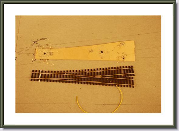
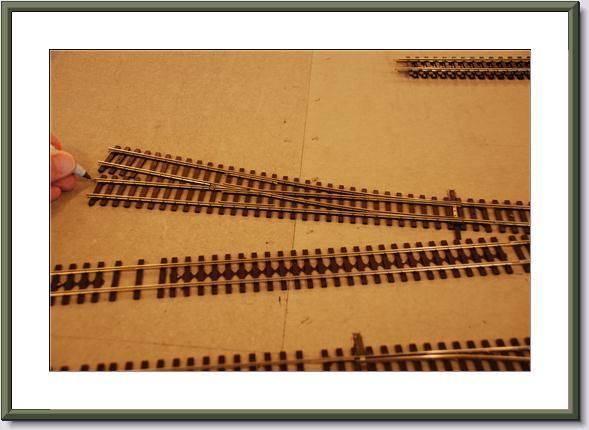
I cut out a template to match the switch [turnout] to aid in drilling the holes in the right spots each time to match where I had the wires soldered.
I mark where the switch [turnout] goes and then lay template down to match the marks.
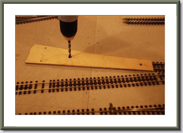
The drill bit size on the small holes is a #20 and the larger holes are a 9/32" drill bit.
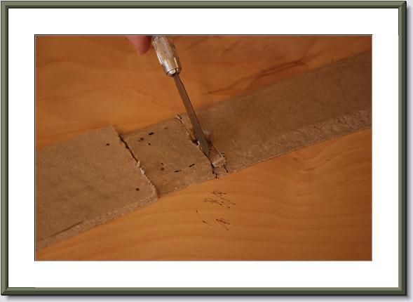
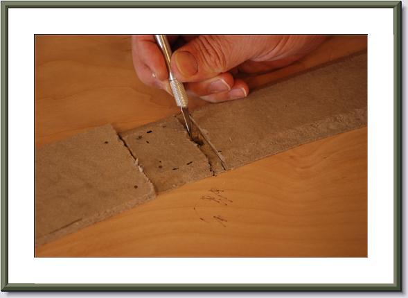
I use homabed from the California Roadbed Company and it has to be cut out so the nuts on the bottom of the cross bar [throw bar] don't rub on it. I first cut using a razor knife.
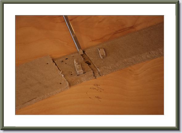
Then I cut it out with 1/4" chisel for wood. I found it is the best way to cut this material.
Then clean out the hole for the Tortoise switch machine piano wire so there is plenty of clearance. You don't want to find out later that the wire is hanging up on something on the edges after the switch [turnout] is installed.
|
Copyright by Allan Gartner 1996 - 2011 © All rights reserved. You may print this for your own, personal, non-commercial use. Non-commercial, non-personal reproduction may be requested by visiting www.WiringForDCC.com/writeme.htm . All users, commercial and non-commercial, may link only to this site at www.WiringForDCC.com. Thanks to all who contribute to this site and the Q&A forum! |