|
||||
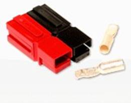
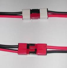
Anderson Powerpoles®, an Alternate Connector for Modular Model Railroad Use Contributed by Doug Stuard, NVNTRAK Introduction For the past 30 years, the published NTRAK standards have proven to be invaluable in ensuring the compatibility of modules assembled from far and wide to build layouts large and small, culminating in the record-breaking Capitol Limited “Mega-Layout” in Chantilly VA in August 2004. For any standard to be effective however, it must accommodate innovation and change. The introduction of DCC and its growing adoption within the N Scale community (and by extension, NTrak) has highlighted some shortcomings in the original NTRAK specifications that could not have been envisioned some 30 years ago when NTRAK was first established. The issue of “DCC friendly” turnouts has received much attention over the past few years, and recommendations concerning turnout characteristics have been published in a number of venues, including Allan Gartner’s excellent Wiring for DCC pages and the North Raleigh Model Railroad Club’s DCC pages. A second aspect of DCC operation, current carrying capability, has highlighted the limitations of the venerable the 2-pin 302 series Cinch-Jones (aka “CJ”) connector used with NTRAK and oNeTRAK modules. The higher currents typically encountered in DCC operation, along with reliability issues, increased cost and reduced availability of the Cinch-Jones connector has prompted a number of groups and individuals to investigate alternatives, particularly for intra-organizational use. The 2-pin Molex connector has had some popularity, as well as the coaxial RCA connector (typically used in audio applications), although no standard has yet emerged among them. While these are all serviceable, and are readily available at the neighborhood electronics retailer, they each suffer drawbacks in durability, flexibility or current carrying capacity, particularly for DCC use. An alternative connector, the Anderson Power Products PP30 series 30 Amp Powerpole® (Figure 1) that avoids these limitations is worthy of consideration. This connector is genderless and exhibits lower voltage drop at the higher currents common in DCC applications in a small form factor. It is economical (less than $1.00 per pair, even in small quantities) and is readily available from a number of on-line sources. In addition, the Powerpole has been proven in similar applications, having become the de-facto standard for DC power connection in the ham radio and public safety (AREC/RACES) communities nationwide (see http://home.comcast.net/~buck0/app.htm). A brief comparison with the Cinch Jones connector is provided in Table 1.
Table 1 – Comparative Connector Specifications
The following paragraphs describe a recommended application of the Powerpole connector for NTRAK, oNeTRAK or similar modular model railroad use. Bus StructuresExisting bus structures are retained (i.e. NTRAK red/yellow/blue/white, oNeTRAK red/white, etc.). 12-gauge stranded copper zip wire is recommended for each bus per North Raleigh Model Railroad Club’s DCC Recommended Practices (either black low-voltage lighting wire with a “rib” molded along one conductor, or red/black zip cord). The length of the bus wire is the length of the module plus a 12 inch extension at each end for connectors. Bus ConnectionsFor red, yellow, blue and other Track Bus connections, the “ribbed” wire (or the red wire in the case of red/black zip cord) is always connected to the front rail of each track as viewed from the front of the module, while the plain (or black) wire is connected to the rear rail of each track. For the white DC Power Bus, the ribbed (or red) wire is designated as the “plus” connection. Connectors and OrientationThe Anderson PP30 series 30 Amp Powerpole® (available from www.powerwerx.com and others) is a genderless connector that can be stacked using dovetails molded into the housings (Figure 1). Unlike the typical DC power application, where + and – orientation must always be maintained, modular railroading occasionally needs to reverse track power connections as modules are reversed in a layout. The genderless nature of the Powerpole connector supports this application. Track Buses (red, yellow, blue, etc.) and the DC Power Bus (white) are connected between modules using connectors at each end of the module as follows:
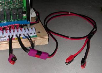
Track Power FeedersConnection from the track power source (Aristo or other DC throttle, Booster/PM42 or other DCC source) should be made using a power feeder “Y” cable. Each cable shall include a Left End and Right End Track Bus connector and a connection to the throttle or booster output, directly or via an extension cable. This “Y” cable is inserted into the Track Bus between any two modules, powering them in both directions. To ensure proper polarity/phasing, the red and black wires should connect to the like colored wires on module track busses. The method of connection of the Y cable to the DC throttle or DCC booster output are left to the user, however vertically stacked Powerpoles, red over black are suggested for the bottom of the “Y” cable, with mating black over red connectors at the throttle/booster output as shown in Figure 7 below. Feeder cables should be labled with violet tape or paint (Figure 8), or with a purple connector housing substituted for the red housing of the set. For Digitrax DCC systems, the red wire should connect to the “Track A” booster output, and black to the “Track B”output.
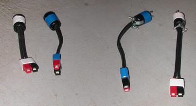
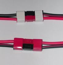
Reversible ModulesUsing Powerpole connectors, it is possible to reverse modules without cross-over wiring or other adapters. This makes reversible corner modules and reversible oNeTRAK modules particularly easy to implement. Figure 9 shows two standard modules on either side of an outside corner module (only one track is shown for clarity). Red/black (front rail/rear rail) integrity is maintained across all modules in this standard configuration. Figure 10 illustrates the mating connectors.
With Powerpole connectors, an outside corner module can be used as an inside corner by simply reversing it in place and connecting the Track Bus connectors black to red, red to black and (in the case of NTRAK) swapping red and blue lines at the interface. Even though the module is reversed, the front rail/rear rail integrity is maintained. Figure 11 illustrates the same outside corner in its reversed position (again, only one track is shown for clarity). The DC Power Bus (white) is not affected. Figure 12 shows the mating connectors for a reversed module.
Part Numbers and SourcesWhile most vendors simply refer to Anderson Powerpole connectors as “30 Amp Powerpoles”, Table 2 lists the Anderson part numbers for the various connector parts that would typically be used in modular railroad applications:
30 Amp Anderson Powerpole connectors are typically packaged in red/black sets, although colored housings are also available. They are available from a number of sources via the internet, including: Powerwerx http://www.powerwerx.com Most of these suppliers also stock 12 gauge red/black zip cord, which makes for a clean installation. Powerpoles are also carried by major industrial electronics distributors, including Newark InOne (http://www.newark.com) and Allied Electronics (http://www.alliedelec.com). ConclusionAs the 2-pin Cinch-Jones connector has become more expensive and less available (i.e., it is no longer stocked at the neighborhood electronics retailer), other connector options have been explored within the NTRAK and other modular railroad communities. With DCC becoming more prevalent, the need for a reliable, higher current capacity connector becomes more important. The Anderson 30 Amp Powerpole® connector is a simple, inexpensive and flexible alternative. It is widely available via internet sources, and has become a de-facto standard for similar applications throughout the amateur radio and public safety communities, thereby demonstrating reliability and widespread acceptance. It has much to recommend it as an alternative (“standard-within-a-standard”) for inter-module connections, particularly when configured as described.
|
|||||||||||||||||||||||||||||||||||||||||||||||||||||||||||||||||||||||
Copyright by Allan Gartner 1996 - 2010 © All rights reserved. You may print this for your own, personal, non-commercial use. Non-commercial, non-personal reproduction may be requested by visiting www.WiringForDCC.com/writeme.htm . All users, commercial and non-commercial, may link only to this site at www.WiringForDCC.com. Thanks to all who contribute to this site and the Q&A forum! |