|
||||
into a Microtrains Z Scale F7 by Glen Chenier, glen@teetertottertreestuff.com So far have used only Digitrax DZ123 and DZ143 decoders,
but any decoder the same size or smaller will work. The Digitrax
decoders are tight, the shell fits afterwards but just barely. The
Digitrax published spec of 3.6mm height for these decoders is slightly
in error - this height is component height with the plastic shrinkwrap
removed - with the plastic shrink left on the decoder height is more
like 3.9mm and will not fit into the MicroTrainsLine F7. 0. While performing this procedure note and return all original parts to their original positions and orientations for wear set retention. 1. Inspect and note any existing damage to shell (paint wear, smears, scratches, cracks in retaining slots or front apron); paint scratches on fuel tank or inside windows. 2. Inspect and note any damage to couplers. 3. Inspect and note any incorrect wheel gauge setting 4 axles. 4. Clean wheels, test run on clean track for minimum speed stalling, excess noise evaluation and possible wobble. Check headlight. Measure motor current if possible now, or later when dis-assembled if stalling is too excessive to allow measurement. Excess current can be caused by mechanical drag, dirty commutator, or shorted winding. While cleaning the wheels (locomotive upside down in
a styrofoam cradle with power applied through
short track section to truck screws) note any excessive wobble of
each wheel when wheel is
pressed against side of truck casting. Sometimes wheels are not perpendicular
to the axle Another cause of wobble is bent wormgear axles. If straightening
attempts later do not work, A final cause of wobble is a loosely held rear truck gimbal. Refer to step 17. 5. Remove plastic shell. Check and note if any stripped threads in lamp and capacitor holders. 6. Dis-assemble right chassis casting half, remove motor. Scope test motor current draw with auxiliary capacitor if not done sooner for excess brush bounce or commutator ripple. 7. Rubbing alcohol (91%) bathe and clean worms, bellgears, shaft bearings, and trucks. If old style metal worm gears replace worms and worm gears/axles with plastic worm gears for noise reduction. Also inspect all gear teeth under magnification for wear and damage. The wormgear tooth profile should be the original convex involute curve, if it has been worn to concave then replace the wormgear and its axle. Inspect wheel axles under magnification for wear. Inspect truck casting slots for wear, the upper curve portion should align with the straight slot portion. If the upper area is rounded beyond the straight portion of the slot the casting is worn and should be replaced to prevent excess axle freeplay. 8. Test motor spur gears and bellgears tightness on shafts. Replace if excessive slip. 9. Smooth corners of each chassis casting in 4 places where bellgear surfaces rub to remove any burrs and snags. Also see step 15 for optional bellgear setting. 10. Check motor brushes with depth gauge in brush holder hole. Replace if wear exceeds 1 mm (1/3 of brush length), indicated by depth gauge penetration of 3mm or more. Inspect slots between commutator contacts. If dirty, clean commutator by shaving a paper Qtip shaft or lollipop stick to fit through the access hole in the top of the motor. Soak this in rubbing alcohol, then press gently into the hole to bear against the powered spinning commutator. Keep doing this, each time cut the dirty end off the cleaning stick and re-dip in the alcohol. When it comes away non-blackened, the commutator contact top surfaces are clean. Now poke a needle or pin through the top motor holes and gently scrape out the debris trapped between the commutator contacts by starting near the bearing and scraping towards the winding. This removes conductive material from between the contacts and will reduce motor current and heating. Do this to all 5 slots. Now when the motor is free-running from an 8-9 volt DC power source the current should be between 80 and 120 mA. Ensure some clearance between the shaft spur gears and the motor shaft bushings. These gears should be tight on the shafts but can slip on the shafts during later re-assembly and drag on the motor. 11. Check truck worm gears for snagging. Rotate by hand and feel for any dragging spots. Trim snagging side protrusions (mold marks) if necessary so that no rough spots can be felt as the gear is rotated. 12. Dis-assemble trucks. Check wheelsets for slipping axles, replace if necessary. Adjust gauge if necessary. Clean axles, truck castings, and sideframes. 13. Replace broken couplers if necessary while trucks are apart. Lube with powdered graphite. 14. If installing WheelWipers do so now. Lube axles and re-assemble trucks. Adjust WheelWiper tension and do final worm gear lube and snag test, trim protrusions again if necessary. ( http://www.wheelwipers.com or http://www.teetertottertreestuff.com). Ensure that the wormgear is not excessively loose between the tops of the truck towers, no more than 0.5 mm clearance. Also ensure truck towers are not pinching wormgear too tightly if in full contact. If outside of these limits check for interfering flash on the ends of the truck castings or foreign particles trapped between the truck castings and the plastic sideframe. 15. Lube motor, worms, bearings, bellgear flats. Ensure slight free play between bellgear flat surface and chassis castings, about 0.5mm. Slide bellgears on their shafts to set this clearance. NOTE: Bellgears have been know to fall off the wormshafts if set to close to the shaft end. The advantage to this setting is that they can be set to avoid rubbing on the chassis casting behind the bellgear flat at their travel extreme and reduce friction. If you want minimum friction and set the bellgears to clear the chassis in both directions of travel, place small drop of liquid CA glue on the inside of the bellgear on the wormshaft end. BE SURE TO PROP THE BELLGEAR IN AN UPRIGHT POSITION WHILE THE GLUE DRIES SO THE GLUE DOES NOT RUN INTO THE BELLGEAR TEETH! This will securely fasten the bellgear to the wormshaft with no chance of it slipping off in the future. 16. Clean and adjust chassis contact whiskers. Set over worm center at slight downwards angle. Two cents more on those contact whiskers. They can be a bit tricky: Make sure a contact whisker has not been grabbed under the worm and mangled. If damaged severely or worn too short from the worm, it may need to be replaced (order from MTL). Just push out the broken one and pull in the new one. Clean all the contact whiskers and truck contact areas where the whiskers wipe on the top tower contacts of the truck. Adjust (bend) the whiskers so they are straight and angled outwards by about 45 degrees. Also angle downwards towards the trucks very slightly, just enough to move freely where they press through the chassis. Now the fun part - getting it back together without
bending the contact whiskers out of adjustment. Make sure the tabs
on the worm
shaft bushings are pointed down into their slots in the chassis.
Lay
the chassis bottom edge against a block of wood about 1" thick
(or
similar vertical edge) to support the trucks straight when they are
laid into the locomotive chassis half. Otherwise they tend to fall
out and we don't have enough hands to hold all this together easily. Now while holding everything together against the wood block, drop the second half of the chassis STRAIGHT DOWN onto the first half. This is important, sliding the chassis into place can cause it's contact whisker to bend or otherwise mis-align. Poke a finger or thumb or tool through the center chassis cutout to hold motor and gears in place at the same time as you jockey the chassis half into position. Should slip on smoothly, do not force. Tighten the screws just snug so as not to strip threads. Now both trucks should power the motor. 17. Re-assemble chassis castings with trucks, replace lamp or capacitor holders if thread stripped. Ensure that the lamp and rear disc capacitor (brown or green arc supressor)wires are fully inserted between the small chassis end protrusions, or the rear chassis ends can touch together and cause an electrical short circuit. Ensure that the top of the motor frame does not touch inside of chassis cutout, shave chassis with sharp hobby knife if necessary for slight clearance to prevent shorting. Test power pickup of each truck in all positions with short hand-held powered track section. Measure at 9volts about 120-180mA free wheeling (power to truckscrews), 150-220mA with slight test track wheel drag. Check that the rear truck gimbal is held firmly captive between the chassis castings, this is what stabilizes the locomotive. If not held firmly, a small amount of solder can be added to the raised round pads molded into the chassis that contact the flat sides of the gimbal. File flat to just high enough to hold the rear truck gimbal firmly. Check that the front truck gimbal has some, but not excessive, free roll to follow track warpage. If necessary (indicated by gear mesh skip during upside down powered wheel cleaning) the front raised round pads can be built up with solder and filed flat to restrict excessive front truck gimbal free play. Older units have insufficient height in these raised pads. The front pads are approximately 0.1mm lower than the rear pads. If the locomotive has a tilt to one side, these same rear truck pads can be adjusted with added solder and filing to seat the rear truck gimbal so the locomotive sits level.
20. Test run on layout at various speeds, note stability, heating, and general performance. Run for at least one hour at about 5 scale mph on torture-test layout with Marklin turnouts, uneven track, 3% grades on 145mm radius curves. Must
not stall a single time. 21. The locomotive must be in good running condition as per the above overhaul procedure.
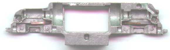
Chassis after modification 22. Completely strip down the chassis castings except for the contact whiskers. 23. Cut away the top rear chassis material both halves to a depth of 2.8mm, or just to the worm cavity top, starting forward at halfway between bellgear cavity and large bearing tab slot. Bevel top of chassis for wire routing to avoid wire insulation damage. Bevel and flatten rear of chassis from top of small bearing tab slot to upper screw hole ridge. This allows the decoder pcb to tilt slightly and clear the large capacitor. Shave 0.25mm off the inside chassis rear to prevent shorting together, no spacer. When the two halves are pressed together before this a gap will be seen between them, they are slightly warped. When enough material (about 0.25mm) is removed the rear warp will be gone with no gap between the chassis halves. 24. Cut notch for motor wire directly above upper hole in motor housing (commutator access hole) in both chassis halves. Notch depth halfway to outer edge of casting to allow wire to clear plastic shell center ridge. Bevel and finish both sides of notch to prevent wire insulation damage. 25. Cut slot for headlight wire just inside of front window both chassis halves at a 45 degree angle extending from top ridge of screw hole to just front of chassis spacer hole. Bevel the front end of this slot to allow wire to clear the lamp holder outer top corners. Bevel the top end of this slot to halfway to the outer edge of casting to allow wire to clear plastic shell center ridge. 26. Cut headlight wires clamp contact area of both chassis castings halfway to outer edge of casting and flush with front of casting to isolate headlamp. Bevel top inside corners to clear wires. 27. Cut the motor brush contacts so they do not protrude beyond the lower portion of the motor housing to isolate the motor. Loosen the brush holders about 1 turn. 28. Wash filings from castings and re-assemble the locomotive, do not install the disc capacitor. 29. Remove the plastic shrink from the PRETESTED DZ123 DCC decoder. Prepare it’s wires by sliding insulation tightly towards pcb to ensure no exposed bare wire sections at pcb. Ensure the wires are properly soldered and do not protrude at or beyond the height of the components.
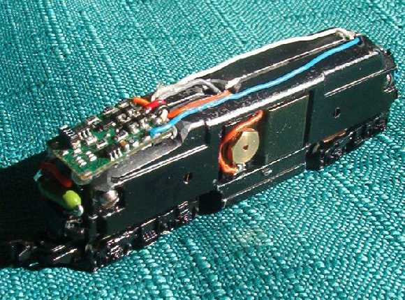
Microtrains F7 with decoder installed 30. Route decoder wires – gray and white along short edge of pcb to opposite long edge, orange along short edge to other opposite long edge, black and red wrapped around to bottom (side without diodes or large capacitor) holding the white, gray, and orange wires in place. Hotglue the red and black wires to route around the sides of the large IC and inside the transistors so as not to add height. 31. Position the decoder on top rear cutout of chassis with diodes upwards towards front and the large capacitor upwards towards rear. In this position the lower side of the pcb is fully insulated by the IC packages so no insulation is necessary against the chassis bare metal. Route the black and red wires downwards (black crossing to left), gray and orange wires through the motor wire notch and out the motor top middle area where they will not get pinched between the motor frame and chassis casting or snag in the spinning rotor, then down alongside the rear of the brush holders with slight excess tucked into the chassis/motor gap. Route the blue and white wires through the headlight slots and out the top corners then down and around the headlight holder. 32. Position all wires, cut to length and prepare ends.
Wires must not cross
over each other on the top of the chassis and must be routed away from the
center of the chassis to clear the bellgears and plastic shell central ridge.
Position and hotglue headlight wires alongside the outside of motor wires.
Solder to the headlight, temporarily remove the headlight holder for easier 33. Install a horizontal 0.375 amp fastblo picofuse (available from http://www.digikey.com part # F823-ND) in the capacitor holder under the decoder pcb with its wire through the right chassis hole in the capacitor holder and cut to clamp under the right chassis half, solder the red decoder wire to the other fuse wire. Use a cutoff fuse wire in the other capacitor holder hole cut to clamp under the left chassis half, solder the decoder black wire to the top of this wire above the capacitor holder. Ensure it cannot touch the fuse itself or its wires. This fuse will blow and prevent further damage in the event of a DCC decoder malfunction. The fuse will NOT protect against shorts between the chassis halves. The fuse wires in the capacitor holder are necessary to space the chassis halves far enough apart to prevent shorting together. 34. Inspect and test with ohmmeter for shorts – solder
bridges to frame,
pinched wires, motor brush tabs not trimmed short enough, chassis halves touching
in rear.
Battery test, then re-assemble the plastic shell and test on layout. |
Copyright by Allan Gartner 1996 - 2005 © All rights reserved. You may print this for your own, personal, non-commercial use. Non-commercial, non-personal reproduction may be requested by visiting www.WiringForDCC.com/writeme.htm . All users, commercial and non-commercial, may link only to this site at www.WiringForDCC.com. Thanks to all who contribute to this site and the Q&A forum! |
 A 1" belt sander with a vacuum dust collection system and breathing
mask to avoid inhalation of lead particles is strongly recommended
(the MTL chassis is a lead casting) when cutting the chassis to accept
the decoder. Lead is poisonous if ingested. When filing one should
avoid smoking or eating until after washing hands to remove lead
filings. When finished vacuum the filings from the work surface.
A 1" belt sander with a vacuum dust collection system and breathing
mask to avoid inhalation of lead particles is strongly recommended
(the MTL chassis is a lead casting) when cutting the chassis to accept
the decoder. Lead is poisonous if ingested. When filing one should
avoid smoking or eating until after washing hands to remove lead
filings. When finished vacuum the filings from the work surface.