|
||||
Kato Turnouts SUGGESTION #2-19: Kato Unitrack Note that there are two Kato turnouts listed below. Also notice that the HO configurations are different than the N scale configurations. Does this mean things are changing at Kato? Maybe; and hopefully for the better. The second style below is fairly slick. If things are changing, you can be sure of two things. 1. Whatever I write today, will be obsolete next week! 2. Do not worry about what size turnout I have listed with each drawing. Figure out which drawing matches the the turnout you have and go with the accompanying suggestions. SUGGESTION #2-19a: Kato Unitrack #4 HO, #6 N. Note: You are reading this correctly. It is not a typo. The #4 HO is like the #6 N. Furthermore, the #6 HO is like the #4 N! This switch is not DCC friendly as is. Fortunately, the point-to-stock rail gap is toy train large, so any rolling stock that will stay on the track will have no trouble at all clearing the points. This turnout power routes the frog rail. Ideally, if the turnout does not power route, you can isolate the track attached to the heel of the turnout from the track leaving the turnout. One way to do this is to use insulated joiners (called Unijoiners). Or you can make an easy modification to your turnout. (Note: This modification was not made to the turnouts sent to me.) 1. Remove the bottom. Be careful! Leave the switch on a table upside
down the entire time you are doing this. Otherwise, its internal parts
will fall out. Something will almost assuredly fall out of place. So
as soon as you open it, see if anything looks out of place and put
it back. That is all there is to it! Making this modification is optional. It will make the frog rails go dead completely. The frog rails will then need to be powered by the tracks they are attached to them. If you do not make this modification, then all the attached tracks will be isolated from the heel only when the turnout is thrown to the other route. Troubleshooting will require more thought. Note: It is not recommended that you power sidings and such through the turnout power routing. The turnout may not ultimately be able to handle all the power that is trying to go through it. You do not have to make this modification, but it is recommended that you power the sidings and such directly from the bus even if you do not make the modification.

As always, I suggest you solder a jumper (called a bond) across the point rails to the closure rails for life-long good electrical contact with the points. Since you cannot make this switch DCC friendly, both points are at the same polarity. Therefore, you only use one bond instead of two. Since the point-to-stock gap is larger than usual, you will have to be sure that the mechanism can still swing the necessary amount after the bond is applied. (Note: This modification was not made to the turnouts sent to me.) While it was easier to show the bond to the side, I suggest you connect the bond from the middle of the point assembly to inside of one of the closure rails. I suggest you remove the point assembly and solder a wire to it. Then use a resistance soldering station to attach the bond to the closure rail. If you do not have a resistance soldering station, you have one other choice or you may need to forget the bond. Any other soldering device will likely melt your turnout. You alternate choice is to drop a feeder down from the point assembly and route it to the internal power routing wiper. Attach it just behind the screw so that it has minimal movement. I suggest you remove the rotating wiper and solder the wire to it rather than trying to solder to the wiper installed in the turnout. If this is too much surgery for you, there is one last thing you can do that will help the longevity of your turnout. Remove only the point assembly screw and lift that end up. You can leave the other end attached to the throw wire. Put some anti-oxidant gel like you put on car battery terminals under the pivot point for the point assembly. Replace the screw. How to Wire This Turnout: This section assumes you have read "How to Wire Turnouts" in the section on turnouts. 1. Connect the frog to your power routing switch or switch machine. 2. Connect your power routing switch or switch machine to your bus to your track bus. If the locomotive shorts when it goes across the frog, swap the wires that connect your power routing switch or switch machine to your bus. 3. Run a wire from from the red stock rail to one of your bus wires. Run the blue stock rail to the other bus wire. 4. The frog rails must also be connected to your bus. You can either connect each frog rail to your bus directly or you can power these frog rails from the track that is connected to them. 5. Optionally, you can connect the bond shown above attached to the point rails. Since this has the potential of making the points too stiff for some switch machines, I prefer to drop a separate wire from the points to the power routing switch or switch machine. Note: You do not need to use insulated joiners anywhere on this turnout. SUGGESTION #2-19b: Kato Unitrack #6 HO, #4 N. Note: You are reading this correctly. It is not a typo. The #6 HO is like the #4 N. Furthermore, the #4 HO is like the #6 N! This turnout is DCC friendly. The N #4 Kato power routing screws on the bottom of the turnout are mislabeled. See this posting on the Kato website: . http://www.katousa.com/consumers/N-4-turnouts.html I show the optional bond for this turnout, but you will be hard pressed to install it. I left it in the drawing so that we have something to discuss. This turnout has a switch motor tucked into its base. It is enough to operate the turnout as designed. However, putting in a pair of bonds is probably too much for it to operate. Usually, when you have a turnout motor that cannot work against a bond, you drop feeders from the points instead. You cannot do that with this turnout because everything that makes it work is tucked underneath. If you drill through this turnout, you will ruin it. I think my best advice is that instead of a bond, put some anti-oxidant gel, like you put on car battery terminals around the pivot to reduce how fast they oxidize. Just wipe it off the top of the rail and flange area.
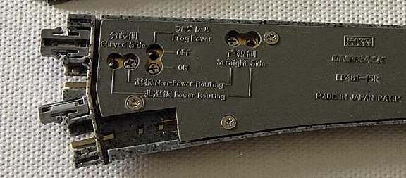
N: Thanks to G. Davis for bringing this to my attention! The Kato Unitrack N scale turnouts are different than the HO. This is a #4. Put the screws in the Non-Power Routing position. You will have an insulated frog if you select Frog Power as OFF. I do not see any reason to do this. Put the screw in the Frog Power ON position. This power routes the frog as we want. There are two additional screws for "power routing." After I analyzed one of these turnouts, this does not do what you would think. The table below describes the effects of these screws. You do not need to understand what is happening (you can ignore the table). In general, you could just put the screw in the power routing position. Interpreting the Power Routing Tables: The two rails leaving the frog are not connected together. No matter how you configure the screws, they never are. In short, "Power Routing" kills a given frog rail when the opposite route is selected. "Non-Power Routing" keeps the appropriate polarity of power applied to a given frog rail at all times.
I suggest that you select "Non-Power Routing." Better yet, make the modification suggested below. I also suggest that you power the track leaving the turnout from the DCC bus. This will make the dead track live again. Your lights and sound will keep working for locomotives sitting on the track that the turnout is attached to. Why suggest selecting "Non-Power Routing?" Two
reasons. Ideally, if the turnout does not power route, you can isolate the track attached to the heel of the turnout from the track leaving the turnout. One way to do this is to use insulated joiners (called Unijoiners). The modification on wiper mentioned above was not possible on the sample N scale turnout I examined. Do not worry about it. How to Wire This Turnout: This section assumes you have read "How to Wire Turnouts" in the section on turnouts. 1. Run a wire from from the red stock rail to one of your bus wires. Run the blue stock rail to the other bus wire. 2. Optionally, you can connect the bond shown above attached to the point rails. Since this has the potential of making the points too stiff for some switch machines, I prefer to drop a separate wire from the points to the power routing switch or switch machine. Note: You do not need to use insulated joiners anywhere on this turnout. SUGGESTION #2-19c: Kato Unitrack #6 N Crossover. Note: The Kato Unitrack I have evaluated is because someone sent me these items. I cannot comment on other Kato Unitrack other than what I can deduce by looking at a turnout in a package at the store. See 2-19a above. Everything that applies to the #6 N turnout applies to the crossover; except that you do not need to worry about the what to do with the rails leaving the frog. All rails in this crossover are powered. A few in the crossover are powered all the time. Others are powered as a result of the power routing. Taking the crossover apart shows a construction that is identical to the turnout shown in 2-19a. Be extra careful in opening this turnout. You have twice as much stuff to come loose at each end. Furthermore, there is a little plastic piece that will come loose. It holds the throw wires down. Here is how it goes back. The three pins go downward (with the turnout upside down). Resist the temptation to put one of the pins in the hole nearby. This hole is for one of the screws that holds the cover on. Instead, slide this little piece away from this hole. It will drop into place and seat itself. The only thing that holds this piece in place is the cover. Except for the two extreme outside stock rails (the long rail than runs unbroken on each side), nothing else is wired through on this crossover. Each inside stock rail for each of the four turnouts will need its own feed.
How to Wire This Turnout: This section assumes you have read "How to Wire Turnouts" in the section on turnouts. Wiring this set of turnouts is identical to wiring the individual turnouts as described at the top of this webpage. 1. Connect the frog to your power routing switch or switch machine. 2. Connect your power routing switch or switch machine to your bus to your track bus. If the locomotive shorts when it goes across the frog, swap the wires that connect your power routing switch or switch machine to your bus. 3. Run a wire from from the red stock rail to one of your bus wires. Run the blue stock rail to the other bus wire. 4. The frog rails must also be connected to your bus. You can either connect each frog rail to your bus directly or you can power these frog rails from the track that is connected to them. 5. Optionally, you can connect the bond shown above attached to the point rails. Since this has the potential of making the points too stiff for some switch machines, I prefer to drop a separate wire from the points to the power routing switch or switch machine. Note: You do not need to use insulated joiners anywhere on this turnout.
Free counters provided by Andale. |
|
Copyright by Allan Gartner 1996 - 2006 © All rights reserved. You may print this for your own, personal, non-commercial use. Non-commercial, non-personal reproduction may be requested by visiting www.WiringForDCC.com/writeme.htm . All users, commercial and non-commercial, may link only to this site at www.WiringForDCC.com. Thanks to all who contribute to this site and the Q&A forum! |