|
||||
Micro Engineering & BK Enterprises Turnouts
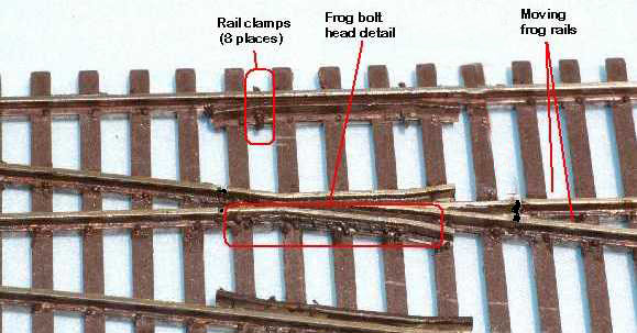
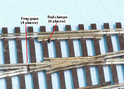
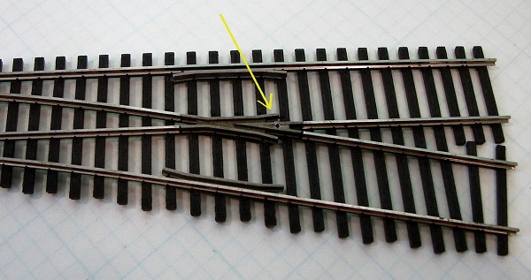
Code 70, 83 #6 only Micro Engineering has arguably the best looking turnout on the market. It not only doesn't have any ugly rivot pivots (hey, that rhymes!), but it's frog includes bolt head detail and the guard rails have rail clamps. So we are very glad to see such a great looking turnout has gone DCC Friendly. Their new turnout has the point rails are at the same polarity as the adjacent stock rails and the frog rail is insulated from the four rails adjoining it. This is precisely what you want in a DCC Friendly turnout. How can you tell if you are looking at a new Micro Engineering turnout? The new package has a white sticker that says "Now DCC Friendly." If you look closely at the frog, you will see that it is isolated.
Weathered frog area highlighting bolt head detail and rail clamps.
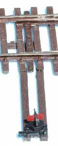
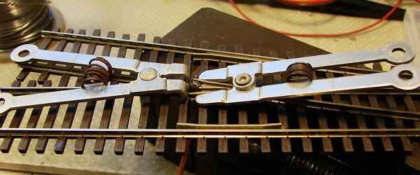
Left: Non-functional switch stand casting. It can
be placed on either side of turnout. The frog is surrounded by gaps from the four rails that lead to it. We found that the two rails leaving the frog moved a bit. This is actually common as we have seen this with other manufacturers. This is NOT a problem with the Micro Engineering turnout. Micro Engineering has molded a small, plastic blade into the gap. So that it is not visible, it is only 0.02" high. Therefore, you can push the rails toward the frog and they will not contact the frog. Once installed on your layout and connected to other track, these rails should cease to move.
You do not have to connect your stock rails to your closure rails. Micro Engineering has a bond on the underside of the turnout that does this for you. However, you will need to power your frog rails. You can do this as shown or power the frog rails from the tracks that they attach to. How to Wire This Turnout: This section assumes you have read "How to Wire Turnouts" in the section on turnouts. 1. Connect the frog to your power routing switch or switch machine. 2. Connect your power routing switch or switch machine to your bus as shown in the above drawing. If the locomotive shorts when it goes across the frog, swap the wires that connect your power routing switch or switch machine to your bus. 3. Option: Run a wire from each point rail to the corresponding bus wire as shown in color above. This is an option for those of us that have experienced problems with turnouts in the past and don't want to take chances. Some of us have had a brush with Murphy and his laws one too many times. Other manufacturers have a rail joiner between their points and closure rail and ultimately develop problems. Micro Engineering's turnout is slightly different in that their points are sprung and they assert that this spring helps maintain reliable electrical contact. You may also want to consider this option if you will remove this spring when using their turnout with a slow motion switch machine. With the spring removed, I can see no difference in their use of a rail joiner and how other manufacturers use a rail joiner as a point hinge. In fairness to Micro Engineering, Ron Rands emphatically states that installing this option is not necessary and that their turnout is ready to use right out of the package for reliable DCC operation. He writes, "It is the rail joiners [between the closure and point rails] that we consider completely reliable for passing current to the switch rails and we have not had any complaints regarding lack of current through them. ... The spring's main purpose is, of course, to provide the sprung switch throw action but it also provides a slight lateral spring action to the switch rails and that is what provides the sprung, wiping action on the rail joiners that keeps them clean and provides reliable electrical contact." Over the next decade or so, I will be conducting resistance tests on turnouts to see which ones develop problems with their points. Check back in a couple of years to see how things are going! Micro Engineering turnout owners write me with your experiences! 4. Run a wire from each stock rail to the corresponding bus wire as shown in color above. 5. Run a wire from each frog rail to the corresponding bus wire as shown in color above.
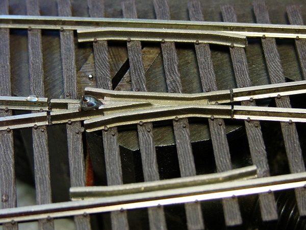
Soldering a Wire to the Micro Engineering Frog Contributed by Jim Exler, Nampa, ID Connecting a wire to the ME cast frog can be a challenge. This is my idea and it seems to work. I decided on 20 gauge (0.032”) solid wire (green of course) for the frog. The 0.9 mm bit I had was hardened to drill circuit boards. With a speed control on my Dremel it worked fine.
2. Next I stripped about 0.25” (6mm) of insulation from the wire and inserted it in the hole from the bottom. I also used a couple of heat sinks I had to protect the tie strip from the heat.
After adding a drop of liquid solder flux (Liquid flux that I've had great performance is available from H&N Electronics https://www.hnflux.com - Allan) to the end of the wire which also went into the hole, I used solid core solder (Using rosin core solder is counter productive when using liquid flux. Solid core solder is also available from H&N as well as most electronic supply distributors. - Allan) and with a 45 watt soldering iron, I heated the joint as quickly as possible to avoid melting the tie strip. The solder seemed to flow with a good “wetting”.
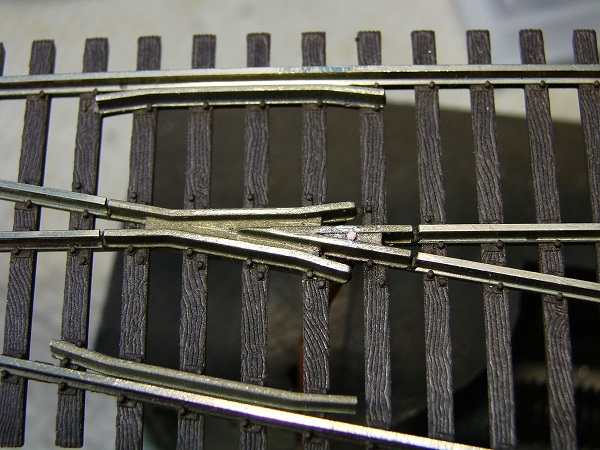
3. I used my rail nippers to remove the bulk of the excess solder and finished up with a knife and a file. As you can see, there is no apparent heat damage to the tie strip or the spike heads.
This is probably best done before the turnout is mounted but I think it can also be retrofitted to an installed turnout.
SUGGESTION #2-4: Making the old-style Micro Engineering Turnout DCC Friendly. Code 83
Note! I forgot to show the connection of the closure rails to the stock rails. Connect red to red and blue to blue. To avoid a short should someone come into the switch with the points thrown against them, I suggest you use a bulb. See section 2-17 for more on the bulb. See the track wiring section for more information on using light bulbs. 1) Remove the throw bar and spring. Replace the throw bar with a piece of circuit board with a cut in the middle of the copper layer. Circuit board can be obtained from Radio Shack, Digikey, or Allied Electronics. See See section #7, "Getting Electronic Parts." See section 2-19 on where to purchase circuit board throw bars. 2) You will need to isolate the points from the frog. Cut these with your trusty Dremel. 3) The rails between the points and frog are called closure rails. Solder a wire between the left stock rail and the left closure rail. 4) Solder a wire between the right stock rail and the right closure rail. At your option, you may completely isolate the frog (5a) or leave the short rails leaving the frog, called the frog rails, attached (5b). 5a) Isolate the frog rails from the frog. Cut these with your trusty Dremel. To power the frog rails from the track attached to the turnout do (5aa) or power them from the stock rails do (5ab). 5aa) Use metal joiners to attach and power these rails from the rest of your track. 5ab) Solder the right frog rail to the left stock rail. Then solder the left frog rail to the right stock rail. 5b) Use insulated joiners to isolate the frog rails from the rest of your track. If you selected this option the insulated joiners are required to avoid a short with the rest of your track. ALSO you MUST power the frog (and the frog rails) as you will have a fairly long dead section if you don't. 6) Unless you selected option (5b), you might be able to leave the frog isolated. It is best if you power route the frog, especially if you have short locomotives or ones that do not have many wheels doing electrical pick-up. If you have a locomotive that has trouble getting over a turnout with an isolated frog, power route it. 7) Remove the throw bar and spring, such as that found on the Micro Engineering turnout. Replace the throw bar with a piece of circuit board with a cut in the middle of the copper layer. I know, I know, the Micro Engineering spring is a nice touch. I hate getting rid of it, too. But I do not see a practical way around it. How to Wire This Turnout - After Modification to DCC Friendly: This section assumes you have read "How to Wire Turnouts" in the section on turnouts. 1. Connect the frog to your power routing switch or switch machine. 2. Connect your power routing switch or switch machine to your bus as shown in the above drawing. If the locomotive shorts when it goes across the frog, swap the wires that connect your power routing switch or switch machine to your bus. 3. Run a wire from each point rail to the corresponding bus wire as shown in color above. 4. Run a wire from each stock rail to the corresponding bus wire as shown in color above. 5. Run a wire from each closure rail to the corresponding bus wire as shown in color above. 6. Run a wire from each frog rail to the corresponding bus wire as shown in color above. Note: You do not need to use insulated joiners anywhere on this turnout. How to Wire This Turnout - As Is, Out of the Box (not pictured here): This section assumes you have read "How to Wire Turnouts" in the section on turnouts. 1. Connect the frog to your power routing switch or switch machine. 2. Connect your power routing switch or switch machine to your bus as shown in the above drawing. If the locomotive shorts when it goes across the frog, swap the wires that connect your power routing switch or switch machine to your bus. 3. Run a wire from each stock rail to the corresponding bus wire as shown in color above.
SUGGESTION #2-5: Making a BK Enterprises Turnout DCC Friendly.Code 40, 55, 70, 83, 100 Note: The BK Enterprise turnout almost qualifies to be in the easy to convert section above. This is because it is not yet spiked down. You will need to use a circuit board throw bar. Considering that the BK turnout will be used by the meticulous modeler, it is essentially easy to make DCC friendly.
Note! I forgot to show the connection of the closure rails to the stock rails. Connect red to red and blue to blue. To avoid a short should someone come into the switch with the points thrown against them, I suggest you use a bulb. See section 2-17 for more on the bulb. See the track wiring section for more information on using light bulbs. How to Wire This Turnout - After Modification to DCC Friendly: This section assumes you have read "How to Wire Turnouts" in the section on turnouts. 1. Connect the frog to your power routing switch or switch machine. 2. Connect your power routing switch or switch machine to your bus as shown in the above drawing. If the locomotive shorts when it goes across the frog, swap the wires that connect your power routing switch or switch machine to your bus. 3. Run a wire from each stock rail to the corresponding bus wire as shown in color above. 4. Run a wire from each closure rail to the corresponding bus wire as shown in color above. 5. Run a wire from each frog rail to the corresponding bus wire as shown in color above. Note: You do not need to use insulated joiners anywhere on this turnout. How to Wire This Turnout - As Is, Out of the Box (not pictured here): This section assumes you have read "How to Wire Turnouts" in the section on turnouts. 1. Connect the frog to your power routing switch or switch machine. 2. Connect your power routing switch or switch machine to your bus as shown in the above drawing. If the locomotive shorts when it goes across the frog, swap the wires that connect your power routing switch or switch machine to your bus. 3. Run a wire from each stock rail to the corresponding bus wire as shown in color above. 4. Place insulating joiners on the two frog rails. |
Copyright by Allan Gartner 1996 - 2019 © All rights reserved. You may print this for your own, personal, non-commercial use. Non-commercial, non-personal reproduction may be requested by visiting www.WiringForDCC.com/writeme.htm . All users, commercial and non-commercial, may link only to this site at www.WiringForDCC.com. Thanks to all who contribute to this site and the Q&A forum! |