|
||||
|
HO Mantua Articulated Logger using a Decoder Buddy Mini
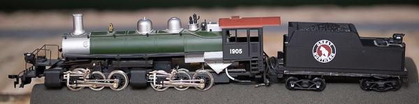
Locomotive is posed on top of the locomotive cradle as it is reassembled. Notice how the tender steps down in the back. This worked against me making the tender smaller. You can just see the coal load recessed into the top of the tender. Introduction Most of my "good" locomotives now have decoders in them. Many modern locomotives either come with DCC or easily accomodate snapping in a decoder. I've also been busy with a job, so I haven't had the need or time to install a decoder in a long time. When NixTrainz https://nixtrainz.com contacted me about looking at their Decoder Buddy Mini, this was a good time to plug in the soldering iron and check it out and a Train Control Systems WOWSound 121 decoder. I presume you are reading this mostly because of the Decoder Buddy Mini and the TCS 21-pin sound decoder than anything else. So if you want to use either of these products, read on. I will then cover the challenges I had with this particular locomotive. Decoder Buddy Mini Decoder Buddy is intended to make easy installation of 21-pin decoders in locomotives that do not already have sockets for these decoders. The NixTrainz website contains more pictures and installation instructions that I will not duplicate here. Here are my thoughts and observations.
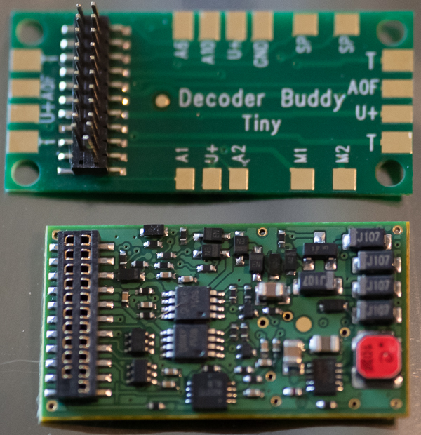
Decoder Buddy Mini The Decoder Buddy Mini is the same width as the decoder and just a little longer in the direction to the left of the pins for the decoder.
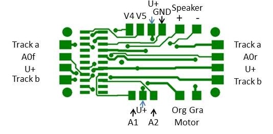
Getting Ready to Use the Decoder Buddy Mini Above is a diagram of the Decoder Buddy Mini. Note that on the right side, there is a connection labeled A0r. This is the connection for the rear tender head light. Note in the photo it is labeled A0F. My Decoder Buddy Mini was an early version and it was mislabeled. That connection is indeed for the rear head light. This mistake has been corrected by NixTrainz. Also note that the name of the product was changed from Tiny to Mini. I mention it here only because if you look at my photo, you may be confused. There is nothing to worry about. Decoder Buddy Mini consists of a mother board, shown above, that is well-suited for installations in diesels or steam locomotives with small tenders. It contains connections for the track (T), speaker (S), lights, a keep-alive circuit (U+ and GND), a few other functions and the motor. Unlike the bigger Decoder Buddy, the Decoder Buddy Mini does not include resistors for LEDs. That worked out to my advantage in this locomotive. I never could figure out how to completely separate the boiler from the chassis and the head light was out on the pilot. So rather than replace the head light with an LED, I decided to keep it. To keep the lights appearing the same, I left the one on the tender as well. So I didn't need the resistors. If you are using LEDs for head lights on your locomotive, you will need a 1,000 ohm, 1/4 watt resistor for each of the head lights you use. Also, when you hook up LEDs, you have to get their polarity right. If you get it wrong, they will not light. So before making your connection permanent, hook them up temporarily and check them. It doesn't matter on which side of the LED the resistor goes. I normally attach mine to the decoder blue wire or U+ as in the case of the Decoder Buddy Mini. The tender in this locomotive presented a real challenge. Initially, it appears large and there would appear like there would be a lot of room inside. But the tender has a large chassis weight that takes up a lot of room. See photos. Also note that the back half of the tender is about half the height as the front. Finally, the height of the front half of the tender is deceptive when you look at it from the side. If you look at the tender from the top, you will notice that the coal load is recessed into it. I didn't let any of this stop me. I was determined to get a big speaker and a decoder into the tender. To test fit things, I mated the decoder to the Decoder Buddy Mini and placed it in the tender. Then I realized I created a problem for myself. Because the Decoder Buddy is almost the same size as the decoder, getting a grip on it to separate them was tough. I pryed them apart with a small screw driver. Don't scratch the electrical traces on the Decoder Buddy Mini or the decoder! Even though I thought I was being careful, I managed to bend some pins on the Decoder Buddy Mini. Lesson: Don't mate the decoder to the Decoder Buddy Mini if you don't have to until you are done. Tender Prep Use a soldering iron with a point tip if you have one. I used a 15 watt soldering iron with a point tip. I still managed to solder a couple of adjacent pads together. I recommend you have a solder pump, sucker, or pull-it - whatever you want to call it - on hand to remove any solder bridges. You can get one from your favorite electronics supplier for $5 or so. I drilled a series of holes in the chassis to let the sound out the bottom of the tender. I also drilled one hole to snake all the wires through that would go to the locomotive. Dress the edge of the hole so that it doesn't cut through the wire insulation. You will notice I have a piece of 0.06" styrene between the speaker and the chassis. This prevents the speaker cone from hitting the chassis when it is producing bass sounds. Installation I had dreams of really short and neatly dressed wires. I found I had to keep some extra length to many of the wires, but definitely not as much as with a directly wired decoder. Another nicety of using a Decoder Buddy Mini is that you can run all black wires between your tender and locomotive. With a wired decoder, you will need to darken the colored wires between the two. If you do run all black wires between the tender and locomotive, be extremely careful to make sure you know which wire is which. You can easily damage the decoder if you don't. I always recommend doing an incremental installation. Hook up the track and motor wires first. Test it. Hook up the speaker. Test it. Then hook up the head light. Test it. Then finally the rear light. But I warned you not to mate the decoder to the Decoder Buddy Mini, until you are ready. So to do a incremental installation with the Decoder Buddy Mini, solder wires to all it's terminals first. Go ahead and attach your speaker and rear head light. Don't strip ends until you are ready for the wires so you don't short anything out when testing. If you use a sugar cube speaker make sure you adjust the volume down before hooking up. Sugar cube speakers can't handle the full power of decoders. Before you power up your installation for the first time, check all your solder connections on your Decoder Buddy Mini are not shorting out to adjacent pads. Be on the particular lookout for tiny solder balls. I suggest you use a magnifying light to do this step. Check adjacent pads with an ohm meter. It only takes a minute or two to do these checks. When done, then mate your decoder to the Decoder Buddy Mini. I recommend that you cut up a a business card and stick it between the Decoder Buddy Mini and the decoder to avoid them touching and shorting. Kapton tape would be better if you have some. NCE sells Kapton tape. I don't like using electrical tape. As time passes, electrical tape loses it's grip and leaves a goey mess. You are now ready to hook up to your locomotive. This goes pretty good. It probably took you longer to read the above than the time it took you to do these things. Which wheel pickups the red and black wires go to doesn't matter. One screws to the chassis of the tender and one goes to the wire that screws to the locomotive frame. Route your wires for the locomotive through the step on the back of the locomotive. If you are installing your decoder into the same locomotive I did, then the orange wire attaches to the motor terminal that is on the bottom of the motor. The gray wire attaches to the top one. Whatever locomotive you are installing a decoder into, make sure the motor terminals are not attached to the frame or you will fry your decoder. Attach two wires for the motor to the mother board, but do not attach them to the motor yet. Instead, clip the wires to the motor. Be sure they don't touch the motor can, frame, or locomotive chassis unless you don't mind damaging your decoder and buying a new one. Power up your track and select address 3 and select the forward direction. The speaker should start making sound. See if your locomotive goes forward. If not, swap the wires to the motor and try again. Once you have the locomotive going forward, power it down and permanently attach the leads to the motor. By now, if your speaker connections were made, you should already be enjoying your sound decoder. You can also test out your rear head light.now. Wire up your front head light. Train Control Systems WOWSound 121 decoder When I first applied power to the locomotive, without the tender shell in place I might add, I was very impressed with how good it sounded. Model railroad sound just keeps getting better. I look forward to spending more time with this decoder. I also look forward to installing a few more sound decoders from other manufacturers to see how they perform. I knew I retired for a good reason - to spend more time with my trains! I also noted that there is a plug in the 22nd position of the WOW121 to keep you from putting it on wrong. So be sure you place your decoder over your mother board and with the connector upward; however counter-intuitive that may be.
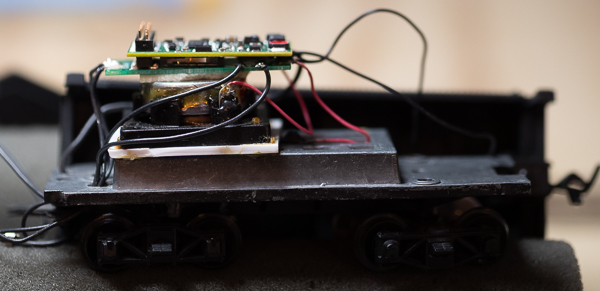
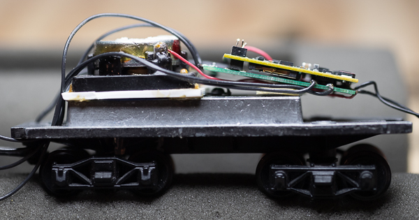
I had intended to place the Decoder Buddy Mini and decoder on top of the speaker, but the coal load in the tender wouldn't let it fit. The large mass that the speaker and decoder are sitting on is the weight for the tender. Note the white piece of styrene the speaker is sitting on. This prevents the speaker cone from hitting the chassis weight. Cut a hole in the center of the styrene for the speaker cone. To the left of the styrene is the hole I drilled for the wires to snake through that are going to the locomotive.
This is where I ended up putting the decoder. It won't sit flat due to the screw in the middle if the weight for the electrical connection. You could move that if you want. After gluing your speaker into place, solder wires to it. Like I said earlier, I was impressed with how good the speaker sounded even before I put the tender shell on. So it is your option if you want to seal the hole for the wires with RTV-type caulk. If you want to use a current keeper (keep alive circuit), solder the blue wire to the U+ terminal on the mother board. Solder the black wire to the GND terminal. Be sure to hook up your keep alive circuit last. If you hook it sooner than as a last step, it will store power and you will have to wait for it to discharge each time you power up the locomotive during your installation. I didn't think I had room for a keep alive circuit, so I didn't get one for this installation. Specific Challenges for this Locomotive I already mentioned one, getting the Decoder Buddy Mini and decoder to fit. I had originally tried to get a standard Decoder Buddy to fit. There was no way it would. I always try out a new locomotive when I buy it. For this model, that was a number of years ago. This model taught me I should have checked it again. The drive train was frozen solid. I found the bushings were frozen on the drive shaft. Just peachy. Not being able to get the boiler separated completely from the chassis got in my way of solving this problem.
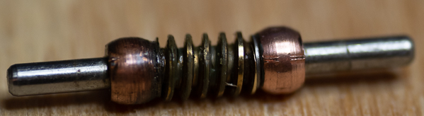
Drive shaft with frozen bushings. When you finally get them apart and turning again, note that there are washers between the bushings and worm gear. I then followed some wise old words. "If it moves and should not, use duct tape. If it doesn't move and should, use WD-40." WD-40 did do the trick of getting the bushings loose. WD-40 may not be safe for plastic, so only spray on metal parts. Then let the parts dry a day before risking getting any WD-40 on any plastic.
Housing for worm gear and drive gear. There is a pair of tiny washers that go on either side of the drive gear (not shown). Don't loose them! Lube the bushings up with some light, plastic compatiable oil and then grease up the drive gear. Put back together and test. Tragedy Strikes! The pin I initially bent was weakened. When I thought I was all done and screwed on the tender shell, the pins hit the shell and the weakened one bent over. It finally happened; after all these years of installing decoders, I let the magic smoke out of one. Fortunately, TCS has a goof-proof warranty. Still, I would have rather maintained my perfect track record of never damaging a decoder. When my repaired decoder comes back, I will trim away the damaged pin and may trim all the excess pin lengths AFTER I mate the decoder to the Decoder Buddy Mini. Close everything up! Enjoy your new locomotive! |
Copyright by Allan Gartner 1996 - 2020 © All rights reserved. You may print this for your own, personal, non-commercial use. Non-commercial, non-personal reproduction may be requested by visiting www.WiringForDCC.com/writeme.htm . All users, commercial and non-commercial, may link only to this site at www.WiringForDCC.com. Thanks r to all who contribute to this site and the Q&A forum! |