Decoder and Soundtraxx Sierra Sound
Installation into a
Bachmann Fn3 (G) 4-4-0
with luck, this also applies to the
Bachmann Fn3 (G) 2-6-0
This installation note assumes you have read the section
on Wiring Specific Locomotives. It also assumes you have read
the section on Sound. Lastly, it assumes
you have read the section on DCC in the Garden.

What you have:
You have a circuit board located in the front. In one way or another,
it drives the flickering firebox circuit. It also controls the headlight
and the non-existent rear headlight. You have all-wheel power pick-up
going to the tender as well as chuff sync.
Bachmann used a rather ingenious method to remove the boiler from
the frame with no wiring for non-DCC users. The wiring from this pick-up
board to the board in the boiler are short. However, the small circuit
board can be squeezed into the boiler so that the front circuit board
comes out enough that you can work on it.
You will find extra contacts in the tender circuit board that Bachmann
is not using. It will be nice when manufacturers start sending the
motor voltage to the tender to run sound systems.
Since this locomotive does not have a rear headlight,
we will rob it's wiring to send the motor voltage to the tender to
trigger the
sound system. Alternately, you can run a pair of wires and a connector
to the tender. If the 2-6-0 has a rear headlight, you will have to
run the extra wires.
Where to put the decoder?
This is a tough choice you will have to make depending on
your personal preferences. You could put it in the tender maybe. Even
if you can shoehorn it and a sound system into the tender, which you probably can
do, it will be tight. This is a small tender - it's not as tall as
some. After all, this was a diminutive locomotive in real life! Worse,
you will have to run 4 wires to the locomotive. Two for the headlight
and two for the motor.
So where do you put it in the locomotive? Not many choices there,
either. Not in the boiler, unless you want to reinvent the flickering
firebox and drive the smoke unit. You can, of course. The flickering
firebox is supported by many decoders and sound units. Remember, my
write-ups are based on what I think the majority of my readers will
want to do.
So the only place left is the cab. Since I live in the rather hot
state of Texas, where decoders in boilers overheat in July and August,
this has become my preferred location. Not pretty, I agree, but no
one notices. They do notice the trains not running!
If you don't like the cab, put it in tender. Just run more wires
to the locomotive from the tender. Or toss the circuit board in the
front. You can always give up on the flickering firebox - a neat effect,
but hardly noticed in the day time.
Either way, the main thing you will get from this web
page is what the wires are for and where to connect things. The hardest
part and most time consuming aspect of any decoder installation in
a G-scale
locomotive is figuring out what the manufacturer provided and how the
installation is to be accomplished.
Decoder Selection
This generic installation instructions can be used with any decoder
made by any manufacturer of your choosing. See Decoder
Selection in the DCC in the Garden section.
Wiring the Locomotive:
The pin numbers are for the Zimo decoder. Note, I do not show
the wires going to the ribbon cable connector on the drawing. I
did this simply because things would be too cramped making the drawing
too difficult to read.
I have drawn a Zimo decoder which does not have NMRA colored wires. So
for the motor and power pick up, I have shown the screw terminal block
that the Zimo MX66S has. The wires shown with the numbers are
the numbers of the wires on the ribbon cable connector that the Zimo
has.
After figuring out how I was going to do this, this locomotive, for
the most part, isn't too bad to install a decoder in. While I ended
up with wires snaking up behind and into my cab and a decoder, this
locomotive is somewhat unique in that you can put it back together
before most of the wiring is done. That's a good thing, because this
is a somewhat smaller than usual locomotive, I found the features,
especially handrails, easy to break. (All G-scale locomotives have
this challenge to a large extent. A very heavy locomotive with fine
features make careful installation a must!)
Separate the motor wires from the wheels. Heck, unsolder them all
for now. Ohm out the wires to make sure you have the two going to motor.
One you can see going to the motor. The other you cannot. Connect an
ohm meter to the one you can see and find the other wire that gives
you a reading. Run these wires out the back and under the locomotive
if you are going to put the decoder in the cab or tender.
Solder the other wires back onto their terminals for power pick up.
Solder on two additonal wires and follow the same route out the back
to power the decoder.
Cut the wires coming from the headlight. They were green and gray
on my locomotive. Add wires to them and run them out the back. Add
a resistor in series with the green wire. I used 680, but you could
probably use 560, instead for a brighter headlight.
Cut the wires for the rear headlight from the circuit board in the
boiler. Put a piece of headshrink over the ends to keep them from touching
anything and shorting. The remaining wire left from this cut is how
we will send motor voltage to the sound unit in the tender.
Put the locomotive back together. Don't forget the rear piece that
fell off from under the cab when you took it apart (see, I've been
there and done that, too!). Putting the locomotive back together is
challenging. I'm not sure why. It's only six screws, but even with
careful routing of the wires, getting the boiler to mate to the chassis
was tough. So go slow and carefully.
Wire up the power pick up to the decoder.
Temporarily wire up the motor leads. Program your decoder and make
sure it runs the right direction. Murphy will make sure you hook it
up wrong the first time, so be prepared to swap the wires! With G-scale
decoders having screw terminals, this is the easiest way to do it and
you don't have to keep track of your colors from your motor as you
go. If you have a decoder that does not have screw terminals, make
sure whatever temporary connection you make doesn't short your decoder.
The four pin connector going to your tender now has two cut wires
on it. These were your rear headlights if this locomotive had them. Making
sure you leave enough length to reach the decoder to the jack on the
tender and going around curves, cut the wires going to your
motor. Now make all your motor connections permanent.
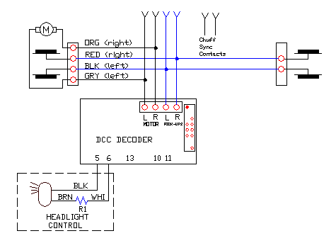
Connect the gray wire (labeled BLK above) to the blue wire (or
pin 5 of a Zimo decoder) - the positive function output of a decoder.
Connect t the green wire through a resistor to the white wire from
a decoder (or pin 6 of a Zimo decoder).
Wire in your headlight and you are done. I ran the headlight wire
behind my decoder so too much wasn't hanging out the cab.
Wiring the Tender for Sound:
Bachmann has stopped making it easy to add sound
and sense power pick up. Luckily, despite no longer providing a connector
for power pick-up and chuff sync, it isn't bad.
Build the power supply circuit for the Sierra. Solder
the wires from the bridge rectifier, Z1, to the other red and
black wires that you follow down to the wheels. While Bachmann did
not provide terminals for you to run your sound system, the brass lugs
for the wheel wiring serve the purpose. Make sure you unscrew a
brass lug from the plastic body or you will melt your tender screw
mounts trying to attach the wire! I suggest you only remove one
brass lug at a time and leave the others mounted on the tender. This
will help prevent you from getting confused about where things go back.
It doesn't matter which wire goes to which wheel.
I build the whole circuit by soldering the parts together
without a circuit board. Using Walther's Goo, I glue the rectifier
to the bottom of the tender to hold everything in place. Remember,
this tender is low on the inside. So build the circuit so the capacitor
can lay in one direction and the voltage regulator, and heatsink if
you use one, in the other direction. In essence, make the circuit flat
or low profile. I put the voltage regulator in front of the speaker
and the sound system behind the speaker. That pretty much uses up all
the available space! If you thought you were going to put the decoder
in the tender, I hope you found a place!
Take the cover off the front of tender connector.
Remove the circuit board and solder your chuff sync wires
to it. This will to be to solder pads and holes for the two pin connector.
Snake these wires into your tender.
The four pin connector has two solder pads in use. The
carry power between the locomotive and tender. The other two were
not used - because they were for the rear headlight this locomotive
does not have. However, earlier, you attached these to your motor leads.
Your sound system will use this to sense motor voltage and trigger
your whistle, airpump, and other optional sounds of your choosing.
So solder two wires to the unused pads of the four pin connector and
snake those into your boiler.
If you want bell and whistle sensors, the underside of
this tender appears to be all trucks! I used home door alarm sensors
that apply to a flat surface with double sided foam tape and attached
them to just inside the wipers of the power pick on the front truck.
Snake these wires into your tender.
A Special Request to Manufacturers:
I don't know of any manufacturer that provides the motor
voltage to the tender for purpose of driving sound systems. This would
be a nice little feature that manufacturers should consider when making
their G-scale locomotives DCC ready. Also would be bell and whistle
sensors, sell them as an option (a money making opportunity for LGB),
or something.
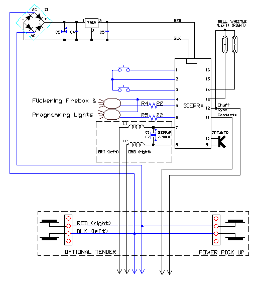
Since the locomotive has a flickering firebox effect, you
certainly don't need to use those with the Sierra unless you want to. So
you do not need to hook up those shown above. The Sierra does
use these lights so that you can program it. So if you did not,
or could not as frequently the case, mount your Sierra in such a way
to see the LED's built onto it, you will need to add lights and the
remote programming switches shown as well. Hide them under a
coal load, or inside a tool box on the tender or locomotive as appropriate.
On this locomotive, I put them in the tool boxes. It was
mighty nice of Bachmann to provide these with working lids!
Instead of light bulbs as shown, you can also use LED's
and 470 ohm, 1/2 watt resistors. LED's theoretically, almost never
burn out. If you do this, make sure you get the polarity of the LED's
right. If you get it wrong, they simply don't work.
Also, instead of a switch to control the Sierra, I go
for a cheap, no-moving-parts solution that I developed for another
locomotive that called for something that was more compact than any
switch. Since it has no moving parts, there is nothing to ever go wrong,
so I stuck with it for the ultimate in reliability. Instead of a switch,
just use a header or a male minature Molex connector with the pins
sticking up. You can cut the pins short if you need to in general.
For this installation inside a tool box, you won't have to. Solder
three wires to the pins using the center pin and wire as a common.
Glue this into the tool box. To use, just short the middle pin to either
of the other two pins with a small screwdriver or pliers.
Use stick on numbers so that you know which pin and light
or LED is which. The LED's on the Sierra are called 1 and 2. The buttons
are labeled + and -. Since stickers for + and - are not readily available,
label the pins 1 and 2 as well. This actually works out better! I can
never remember whether it is + or - that puts the Sierra in programming
mode. But I do remember that LED #1, indicates which feature is being
programmed. So I label the pin that causes LED #1 to flash, 1. Some
things are just too simple!
You have to hook up the wires for your motor sense voltage.
Murphy will again make sure you hook them up wrong the first time.
Luckily, the Sierra has screw terminals, so you don't have to worry
about Murphy and his dirty deeds today!
In talking with the folks at Soundtraxx, they suggested
I try hooking up the motor sense wires without the filter circuit I
show (L1, L2, C1, and C2) because I was using a Zimo and they had,
had good luck with not needing the filter with them. Given this was
a low profile tender, I was game for trying this. For all of us, this
makes things a little less expensive. I hooked the motor voltage leads
straight to the motor sense inputs, pins 7 and 8. At least on the bench,
things appear to be working fine. You may or may not have to use it
with the decoder you select.
Components
C3: Electrolytic capacitor, 100uF or more rated at 50V or more.
C4, C5: 0.01uF, 50V ceramic capacitors.
7812: 7812 12, 1A voltage regulator. If possible, mount
to metal inside your locomotive. However, it must be electrically
isolated any other electrical device also using it for cooling. Otherwise,
you will let the smoke out of something and ruin it, as well as your
day.
Z1: Any bridge rectifier good for at least 1A and 50V.
R4, R5 should be 22 ohm, 1/4W resistors.
R1,R3: Already present.
See the section on Getting Electronic Parts.

Free counters provided by Andale.
