|
||||
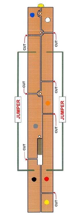
Atlas S-2 by John V. Baum J V Baum@aol.com Installation of a Digitrax DN140 in an Atlas S-2 Locomotive: These instructions and the diagram are based upon instructions for the installation of a DN93 decoder in an Atlas S-2 provided by Robert Savard of North Palm Beach, Florida and appearing among those decoder installation instructions appearing in the Loy's Toys website. The DN93 decoder does not include the blue, or common, decoder wire for forward, reverse, or special effects lighting. The additional cuts in the printed circuit board material contained in these instructions are necessary if the blue, or common, wire is going to be used by the installer. 1. Remove the grab irons, cab, and shell from the locomotive.
2. Refer to the diagram. Make cuts through the plating on the printed circuit board material approximately 1/8" in width. This is best accomplished by using an X-Acto knife to score the board on both sides of the cut, and then using the tip of the blade to either peel the material to be removed from the board or, in the alternative, to scrape it away. You do not want to make your cuts completely through the printed board material; the object is to score completely through the metal plating to the surface of the board and no deeper. 3. The cut to the immediate right of the point of attachment for the yellow decoder lead is optional, and need not be made if you do not intend to install a rear headlamp. If you wish to install a rear headlamp, a rotary beacon or other special effects lamp in the locomotive, go ahead and make the cut to create a point of attachment for the yellow, brown, violet or other special effects lead from the decoder. 4. Remove the headlamp from the center of the wiring board. Slide a short piece of heat shrink tubing over the free ends of both copper wires to a position immediately above the motor brushes. Reposition the copper wires beneath the plastic retainers, and reattach the truck leads to the ends of the copper wires. 5. The decoder must be installed within the interior of the cab. I cut a piece of thin styrene sheeting to conform to the interior dimensions of the cab, and test fit the resulting rectangular "flooring" into the cab from the bottom. The clear plastic windows will act as a stop and prevent the styrene part you have fabricating from rising past the bottoms of the windows. (Depending on the depth of the sheeting you use, it may also prevent you from re-attaching the cab to the locomotive frame once installation has been completed. Should that occur, file or otherwise trim material from the bottom edge of the clear plastic windows to compensate for the depth of the sheeting. 6. Remove the "flooring" from the cab. The decoder will sit on top of the flooring. Drill a hole in the flooring to permit the decoder leads to pass through that hole. Paint the flooring a dark color of your choice. When dry, feed the decoder leads through the top of the flooring, and secure the decoder to top of the flooring with foam tape. The decoder is red, and will be visible through the cab windows. To minimize its visibility, cover the exposed area of the decoder with black electrical tape. 7. Press the flooring, decoder side up, back into the cab. The decoder leads should be positioned to run from under the flooring towards the front of the locomotive. Referring to diagram once again, solder the various decoder leads to the printed circuit board material where indicated. Although you will need to shorten the leads in order to avoid a tangle of wires once the installation is finished, do not shorten them to such an extent that you will later be unable to remove the cab without breaking the leads to the circuit board. Install jumper wires where indicated on the diagram. 8. If you don't intend to install a rear headlamp, it is not necessary to solder the yellow decoder lead to the board. 9. I did not replace the factory installed headlamp in my S-2. I simply attached the white and blue decoder leads to the board where indicated. Nor did I install a rear headlamp. I did install a rotary beacon by drilling a hole in the roof of the cab for the beacon bulb, and running the leads from the beacon through the hole in the flooring referred to above. One lead from the beacon was soldered to that portion of the circuit board where the blue decoder lead is soldered. The other lead from the beacon was soldered to the circuit board reserved for the yellow decoder (If you wish to install both a rear headlamp as well as some other special effects bulb, solder one lead from the special effects bulb to the area on the board reserved for the blue lead, and the other lead directly to the decoder lead, using heat shrink tubing to insulate the connection. 10. Reinstall the shell, cab and grab iron in that order. |
Copyright by Allan Gartner 1996 - 2010 © All rights reserved. You may print this for your own, personal, non-commercial use. Non-commercial, non-personal reproduction may be requested by visiting www.WiringForDCC.com/writeme.htm . All users, commercial and non-commercial, may link only to this site at www.WiringForDCC.com. Thanks to all who contribute to this site and the Q&A forum! |